Synchro Points
Presentation
 | The synchro points are positioned on 2 profiles to machine in order to force the wire path between them in 4 axes mode. |
There are 3 steps to position synchro points :
Define the 2 profiles
Make an outcome to check if we need synchro points
Define synchro points with automatic, manual or combined mode
To define profiles
1/ Define the profiles
Do a selection box or click on the 2 profiles one after another.
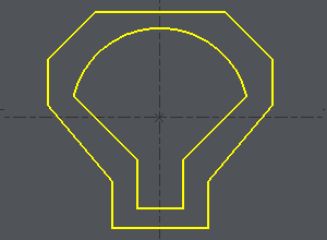
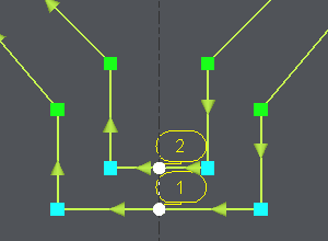
To define the starting point on the middle of an element like shown in the example :
Click on the profile,
Click on the starting element, move the cursor along the element and click where you need the start or choose the START or the MIDDLE of the element with a click on the button : here choose MIDDLE
Click on the ending element (in the example the same element), move the cursor along the element and click where you need the end or choose the MIDDLE or the END of the element with a click on the button: here choose MIDDLE.
 |  |
2/ Outcome
Once the profiles are done, the dialog bar appears : Click on About the profile [1] . A message box give you the characteristics of the 2 profiles selected, number of elements, number of synchro points.
3/ To define the synchro points

About the Profile | |
Inversion of direction of the selected profile | |
Adding Synchros - Manual creation of synchro points | |
Automatic creation of synchro points between 2 zones. Click on the button 'All' and the creation is automatic for the whole profiles. | |
Deletion of a synchro point by clicking on it. | |
Cut of an element |
Click on the green tick 'Other profile' to confirm or create synchro point on 2 others profiles.
Click on the red cross to cancel all the synchro points created.
When creating synchro points we can combine manual and automatic creation. This is what is explained in the second example above.
Automatic method
Click on [1] . There are 7 elements on a profile and 11 in the other one. It can be machined with the cycle 4 axes contour/contour but it is not optimized. If you want to optimize the toolpath, you have to set up synchro points. | |
The synchro point can only be defined on existing points or elements extremities. You have to cut an element : click on [6] and then click on the arc, you can move the cursor all along the element, click on the screen when you want to cut. A circle (tangency) or a square (sharp angle) is displayed where you cut. | Cut of the arc with the white cursor 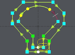 |
The number of elements is now the same on the 2 profiles : Click on [4] and then click on 'All', all the extremities of the 2 profiles are linked 2 by 2. | The synchro points are created automatically 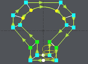 |
Manual and automatic methods combined
Let's take an example identical but with 2 corners more. Here we will have to create double synchro points and this is not possible in automatic mode :
Click on [1] to have information about the 2 profiles. | 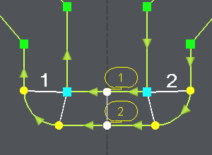 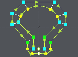 |
Click on [3], click on the angle (blue square) and click on an extremity of the corner (yellow circle), click again on the angle (blue square), a message warns you about the creation of a double synchro point, click on OK and click on the other extremity of the corner (yellow circle). Repeat the same operations on the other corner. | |
The synchro point can only be defined on existing points or elements extremities. You have to cut an element : click on [6] and then click on the arc, you can move the cursor all along the element, click on the screen when you want to cut. A circle (tangency) or a square (sharp angle) is displayed where you cut. | |
We want to create synchro points between the 2 corners already treated : click on [4], click on the 2 synchro points already defined (1 and 2 on the image) to limit the zone to treat, all the extremities of the 2 profiles are linked 2 by 2. |
Once the synchro points are set up, click on [1] to obtain information for the synchro points created , if the machining is possible you are told about it. Then you can go to the machining editor and choose the cycle 4 axes cnt/cnt.


