
Cycles: Jig Boring, Drilling, Tapping, Counter boring, Reaming, Threading, Toolpath
Definition
|
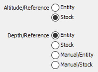
These two parameters allow you to define the altitude and the depth from the geometric reference. There are 8 possible cases, described in the next table. |
|
|
Altitude/Ref: Entity Depth/Ref: Entity |
Altitude = Z entity + SD. Depth = the depth of the entity, if this one have a depth. If it is not the case, the functioning is the same that Entity+Manual/entity. |
Altitude/Ref: Stock Depth/Ref: Entity |
Altitude = Z stock + SD. Depth = the depth of the entity, if this one have a depth. If it is not the case, the functioning is the same that Stock+Manual/entity. |
|
Altitude/Ref: Entity Depth/Ref: Stock |
Altitude = Z entity + SD. Depth = through hole. |
Altitude/Ref: Stock Depth/Ref: Stock |
Altitude = Z stock + SD. Depth = through hole. |
|
Altitude/Ref: Entity Depth/Ref: Manual/Entity |
Altitude = Z entity + SD. Depth = the depth is given from the entity by the value entered in the panel. |
Altitude/Ref: Stock Depth/Ref: Manual/Entity |
Altitude = Z stock + SD. Depth = the depth is given from the stock by the value entered in the panel. |
|
Altitude/Ref: Entity Depth/Ref: Manual/Stock |
Altitude = Z entity + SD. Depth = the depth is given from the stock by the value entered in the panel. Used for a centering. |
Altitude/Ref: Stock Depth/Ref: Manual/Stock |
Altitude = Z stock + SD. Depth = the depth is given from the stockby the value entered in the panel. Used for a centering. |
|
|
The parameter Depth enables to define the depth retraction from the reference. You can modify this parameter only if you select Entity, Stock or Manual/Stock in Depth/Reference. This value can be positive or negative. |
Special Feature
If Altitude/Ref and Depth/Ref are both set to stock, there are a few features to consider:
-
the Rapid plane alt. value is still defined with respect to the origin of the stock.
-
however, the Safety distance is now dynamically related to the stock; the computation takes into consideration any pre-processing on the stock.
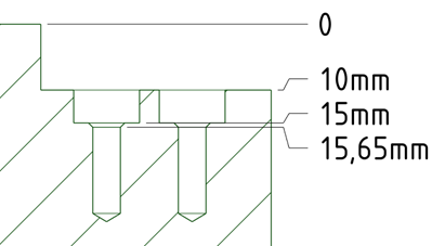
For instance, let’s consider this image. The Rapid plane alt. is set to 15mm and the Safety distance is 2mm. The safety distance for the drilling cycles is lover than that of the stock.
The resulting processing of the drilling cycles is as per below:
|
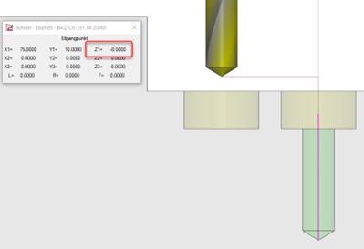
Pre-positioning to the Rapid plane alt. of the stock at Z15. G00, G90, G54, X88. Y10. G43 H... Z15. |
||
|
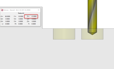
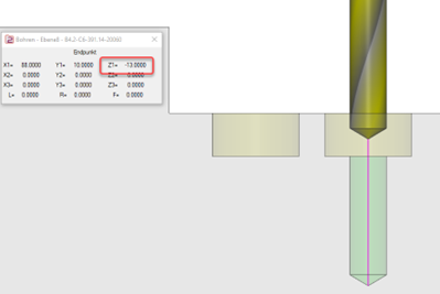
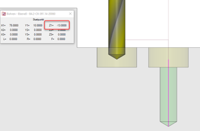
Motion to the Safety distance Z -13 in the counterbore - 2mm above the drill operation followed by the drilling process with subsequent retraction to that safety distance. G99, G81, Z-30. R-13. F... |
|
|
|
Retraction to safety distance Z -8 just above the stock (2mm above the level of the bore) between the drill cycles to position for the next operation. G80 Z-8.X75. |
|
|
|
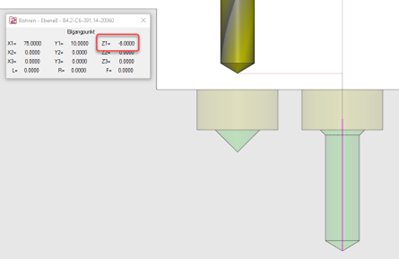
Repetition of drilling cycles G81 Z-30. R-13. F... |
|
|
|
At the end of the drill operation, the tool retracts to the Rapid plane alt. level at Z 15 G80 Z15. |
||
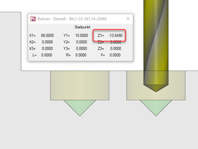
For the case where a chamfer is defined and pre-machined for the counterbore, the calculation of the safety distance takes into account the chamfer resulting in the safety distance for the drill being slightly deeper, for instance at Z -13.65 rather than Z -13 in the example. The switch between the drilling cycles are still carried out at Z -8, hence a safe flow is guaranteed.
|
|