Skip table of contents

FAQ - Tooling

(question) Question

Can we manage Flash tools in GO2cam?

(tick) Solution

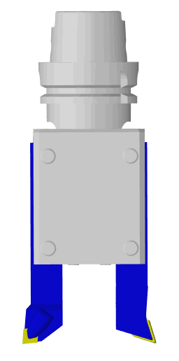
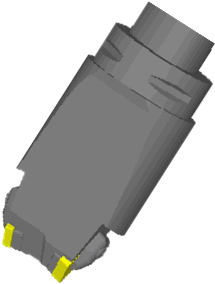
What we call Flash tool is the concept of multiple tools mounted on one single holder, usually, 2, 3 or 4 tools.

We can manage them easily in GO2cam, by following some rules to create tools and apply machining:

  1. Creation of Holder:

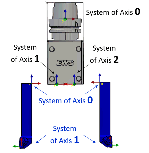
  • create the system of axis 0 as the point to clamp the holder into the spindle.

  • create the systems of axis 1 and 2 as positions to receive the tools. Z to the top, X to the back. Those systems of axis must fit with the systems of axis of insert holders, as shown on the image.

  1. Machining

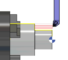
Programming of operations is done with the tool without holder. Here we program a roughing operation (insert C) and a finishing operation (insert D).

  1. Mounting the tools

In MTE Tooling menu, the 2 tools are waiting for being mounted. With a right-click on the spindle tool support, you can choose ‘Add > a solid toolholder’. Select the flash tool.

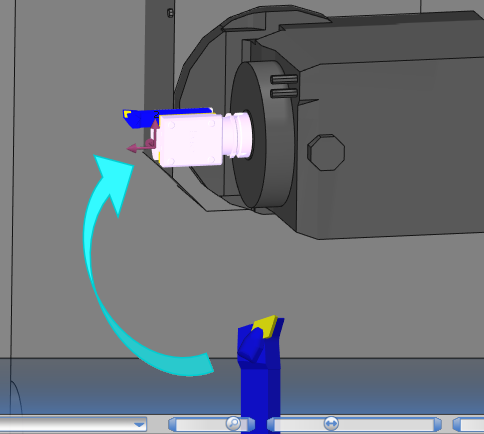
Now you can simply drag & drop the 2 tools on the 2 positions of the holder.

In the machine kinematics, the spindle must be defined with a B rotation axis, to be able to index the Flash tool!

(question) Special Case

Can we also manage Flash insert holder?

Here, the Flash holder is an insert holder.

Problem: the insert holder is part of the tool. We cannot use the same method presented above to pilot this type of tool.

(tick) Solution

The solution is to build this insert holder as it was 2 insert holders + 1 holder:

  • 2 insert holders: no solid of holder, only the systems of axis to position the inserts. Warning: a ‘fake’ solid must be present in the file so that the symbols can be created.

  • 1 holder including the solid.

Once the symbols are created, you can program the operations by adding insert holder + tool holder in each of the tools.

In MTE tooling menu, you should break out the 2 tool holders and finally build one only tool: please watch the video to follow the complete process!

You can also download holders symbols here: Double insert holder.zip

Double inserts-20240812-121542.png

(minus) Issue

Why does the system add ‘_1’ at the end of the tool name on the application of an opelist?

(tick) Solution

Explanation of the problem:

The opelist includes the tools 'X5-Flat End Mill - D08 - R.F05' and 'X5-Flat End Mill - D08 - F.F05 that are also present in GO2cam tools library. This opelist has been created some times before or even a day before.

In the mean time, there may have been some changes done to the tool in the tools library. These changes can be differences in dimension or even simply a comment for instance.


On applying the opelist in the current project, these differences between the current tools library and the tools saved with the opelist are detected and In such cases, the system, adds '_1' at the end of tool name.

This issue in turn extends to the MTE environment and cause issues in the auto-mounting of tools with the tool numbering.

Opelist.PNG
Machine tree Cycles.PNG

How to fix it?

To prevent this situation, there is one option in the Opelist menu, called 'Tools Update'. It enables to update the tools in the opelist compared to the tools in the library.
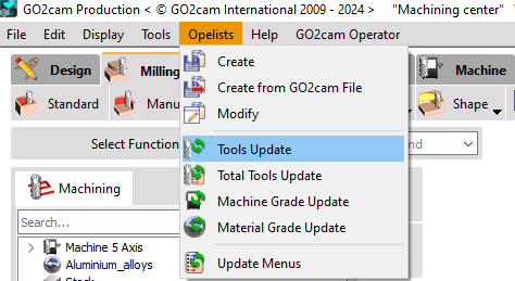
Tools Update.png

Simply click on it, select the opelist you want to update and click on open to update it.

Machine tree Cycles - resolved.PNG

(question) Question

What are barrel tools, what types are available, and for which operations/machining cycles are they applicable in GO2cam?

(tick) Answer

Barrel tools, unlike traditional end mills or ball nose cutters which have a cylindrical or spherical shape, feature a curved, barrel-like geometry. This design provides the tool with multiple radius profiles and has several advantages in machining, particularly in complex and high-precision applications. The main advantages of the tool are as such:

  1. Reduced Machining Time: The large effective radius of barrel tools allows for larger step-downs and fewer passes, significantly reducing machining time.

  2. Improved Surface Quality: The curved profile of barrel tools ensures a better surface finish, as it can maintain contact with the workpiece over a larger area.

  3. Increased Tool Life: Due to the reduced cutting forces and optimized engagement with the material, barrel tools generally have a longer tool life compared to traditional cutters.

  4. Efficiency in Complex Geometries: Barrel tools are particularly effective in machining complex, freeform surfaces often found in aerospace, automotive, and mold-making industries.

The types of barrel tools and the cycles in which they are available are detailed below:

obl468 - Lens Mill Cutter.png

Lens Mill Cutter

Milling>Shape>Automatic: millyuGO, Roughing/Reworking, Facing Roughing, Pocket, Facing, Finishing

Shape milling>Rough/Rework: Roughing, Rough Reworking, All finishing cycles except Spiral and Finish Reworking, Profile projection, 5X Expert cycles

obl467 - Oval Mill Cutter.png

Oval Mill Cutter

Shape milling: Finishing - Z Level, 5X Expert cycles

obl466 - Barrel Mill Cutter.png

Barrel Mill Cutter

Shape milling: Finishing - Z Level, 5X Expert cycles

obl469 - Lens Barrel Mill Cutter.png

Lens Barrel Mill Cutter

5X Expert cycles

obl470 - Taper Barrel Mill Cutter.png

Taper Barrel Mill Cutter

5X Expert cycles

You can watch an introductory video on the right.

Barrel tools-20240812-121652.png

(question) Question

How to carry out threading operations with varying pitches?

(tick) Answer

In the tool page for Thread Mill Cutter, we can define a range of pitches.

Mechanism for calculation:

  • Set the range of pitches to Yes,

  • Maxi pitch option is activated.

  • The ‘Mini pitch’ is determined by (TP) Pitch value

  • The cutting length is automatically forced to the value of mini pitch,

  • Number of flutes is automatically forced to 1.

Tool Parameters.PNG

In the strategy page of Threading, the pitch field becomes activated. You can only enter a value within the range of the Mini pitch and Maxi pitch defined in the tool page, else you get an error message .

Thread Parameters.PNG

The advantage is that the same tool can be used to machine several holes of varying pitches. See a video on the right showing the application of these parameters.

Multi pitch threading-20240812-121737.png

JavaScript errors detected

Please note, these errors can depend on your browser setup.

If this problem persists, please contact our support.