Machining Features GMF
Introduction
General Machining Features (GMF) is an optional module enabling the automatic calculation and generation of adequate toolpaths to machine a solid prismatic part.
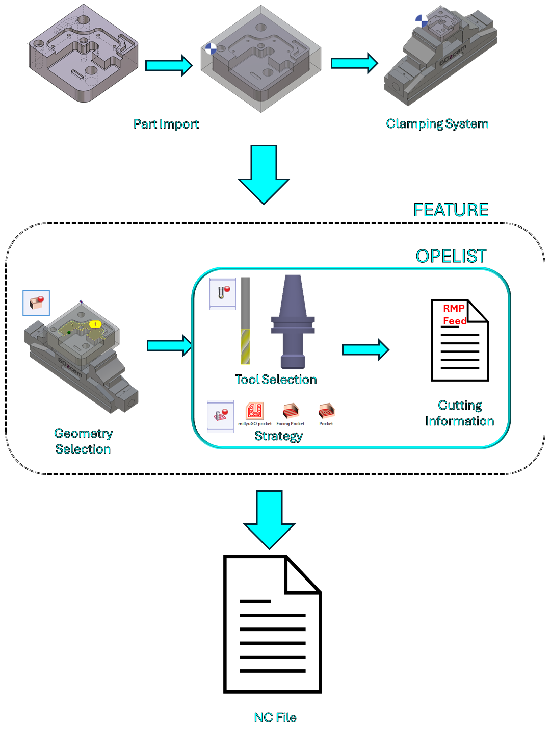
A typical process workflow on GO2cam is shown on the right. It can be summarized as such:
Among these, the 2nd step is the most time-consuming. The Opelist regroups some of the actions such as the Tool and Strategy selection and definition of Cutting information. This helps to reduce manual actions required in the workflow. The introduction of Milling Features further reduces the manual actions required for the machining of a part. This automatic feature option is almost a one button click application that upon launching will:
Only Prismatic topologies are automatically recognized and machined!
|  |
Using Features
 | The command Features is available in the Design tab, under the Solid menu. | |
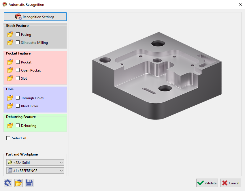
 | Choose the icon Automatic Recognition from the submenu on the left of the screen to launch the automatic recognition window. This window can also be launched, if no feature recognition has been carried out in the Design environment, directly in the Milling tab under the Hole/Feature submenu and selecting Automatic. You will be prompted with an error message.  Upon clicking OK, the Automatic Recognition window will be launched. The features are based on multiple calculation:
|  |
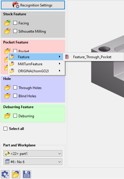
Those features are linked to predefined opelists. This is indicated by the orange bubble on the folder icons. If you click on the folder icon for the respective feature, you can choose from a list of other opelists, provided that they have been defined properly, prior to the application of the feature. If you manually select the opelist in this manner, the bubble becomes green in color. You can check the boxes individually for the required features or select all. Then click on Validate to run the process. A list of all the features selected will be provided with the automatic selection of tools and strategies. Simply click on Calculate to run the machining calculation. (If Feature recognition has already been done in the Design environment, on selecting Automatic under Hole/Feature in the Milling tab, you will be brought directly to this window)
|  | |
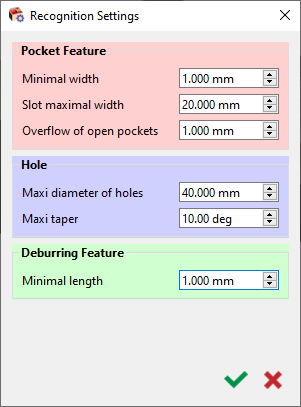
 | Recognition Settings Window: This Recognition Settings window has been added as from V6.11. It allows to set some preliminary parameter values for the recognition of Pocket features and Holes. You can define the minimum width to recognize a feature as a pocket Similarly, a maximum width for slots, a value beyond will be recognized as a pocket. One more interesting aspect is that you can now define an overflow for through pockets, ensuring the pocket depth is fully machined. You can also set the maximum diameter and taper angle to recognize a feature as a hole. A minimal length can also be set onto which deburring will be applied. |  |
 | The configurations in the Recognition Settings and the main Automatic Recognition window can be reset by clicking on [1]. These configurations can also be saved [3] and reloaded [2] for application on another part. | |


