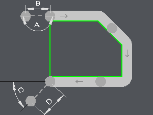
Lead in and Lead out in XY
Cycles: Contouring, Contour rework, Slotting, Chamfering, Taper cutting, Profile cutting, Chamfering
Definition
This box allows you to regulate the tool approach in rapid speed.

A. Leadin angle
B. Leadin length
C. Leadout angle
D. Leadout length
A. Leadin angle
Leadin angle together with leadin length define the leadin movement of the tool in feed rate. This movement is necessary for the tool to take its diameter compensation ( G41 or G42 ). The value of the leadin angle is between 0 and 90 degrees.
It is the leadin angle value of the tool. If the offset or the Toolpath is at the Left or to the Right, the angle is given in absolute value relative to the first element.
If there is no offset (center position) and if the toolpath is in Part position, the angle is given in absolute value according to the counterclockwise circle.
The length is given by the leadin length.
B. Leadin length
The value for leadin length must be greater than the radius of the tool. This value is based on the angle line, not on X or Y.
C. Leadout angle
Like leadin angle and length, leadout angle together with leadout length define the leadout movement. This movement is necessary to cancel the diameter compensation of the tool. The value of the leadout angle is between 0 and 90 degrees.
It is the leadout angle value of the tool. If the offset or the toolpath is at the Left or to the Right, the angle is given in absolute value relative to the first element.
If there is no offset (center position) and if the toolpath is in Part position, the angle is given in absolute value according to the counterclockwise circle.
The length is given by the leadout length.
D. Leadout length
The value for leadout length must be greater than the radius of the tool. This value is based on the angle line, not on X or Y.
