Nesting in milling
Presentation
 | The nesting is an optional module that enables to optimize the positioning of multiple shapes in a stock. The geometries to be nested are only solids! It is available in the menu Design / Nesting. |
The objective is to optimize the positioning of part to save material. Then you can set connectors to maintain the shapes and finally use the automatized cycle of cutting.
Principle
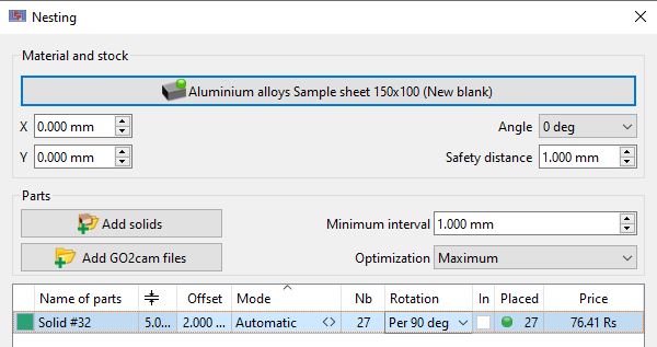
Parts: when you run the nesting command, the solids on the screen are automatically selected. They appear in the list and a color is applied to each of them. You can import any type of solid CAD format files with the button ‘Add solids’. For the nesting calculation, you have to define a minimum interval between the solids and also a level of optimization, standard, intermediate or maximal, on which depends the time calculation. Material and stock: to start the nesting, you need to choose a material and a block. X and Y position: the origin of the stock is determined by the fields X and Y. Angle: enables the positioning of the block. Safety distance: is a margin all around the material. In the list of solids: The Offset value enables the creation of 2 curves, the toolpath will be done in between. Nb: is the number of parts to place, Rotation: you can allow or not the rotation of different solids for the positioning: we can choose a free rotation (all the possible positions), 0 or 180 degrees, per 90 degrees or no rotation. In: the hollow shapes are recognized by GO2cam, check the box to position other elements inside. Placed: it shows the number of elements positioned, the solids which are not completely placed are pointed out by a red balloon. | 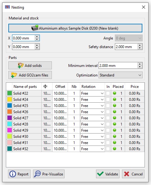 |
Calculation: the button ‘Pre-Visualize’ enables to check the result according to the adjustments and chosen values. You can do modifications and run pre-visualization as many times as necessary. After applying the ‘Validate’ button, the solids are duplicated and the curves and profiles are created. The button ‘Report’ enables to print the table or to save it in an editor. | |
The heads of columns are accessible, you can enter a value and so apply it to the full list of solids.
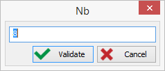
Here, we define the number of 8 elements to place for each solid of the list.
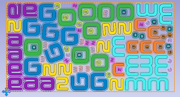
Pre-visualization of the nesting of GO2cam letters, in 2 different sizes:
 |  |
Special Case: 1 only solid
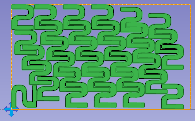
If there is only one solid to place, a new column ‘Mode’ appears and enables 2 types of calculation:
Value, to define the number of elements to place,
Automatic, to place as many elements as possible in the selected stock.
After calculation, the number of placed elements is displayed!
 |  |
Features
- In the table, by a right-click on a solid, you can create its symmetrical solid and then use it in the nesting,
- During pre-visualization, the colors are automatically applied for a better recognition of the placed elements,
- By giving first a price to the material block, we can calculate the unitary price of each part,
- The offset curves are placed automatically in the layers 12 and 13, to configure opelists with automatic references,
- We can used stocks already machined and manage a library of materials.
You can also nest pre-programmed PCE files.
You can also define the external machining (separating cut) in the individual part.
In this case, however, it is not possible to react to the holding bars that were added during the nesting process.
Other commands
 | Set connectors | Choice of the type of connectors and set on the elements. It is possible to position a connector on a solid and to duplicate automatically this connector on all the identical solids! |
 | Management of connectors | Creation of new connectors, with rectangular or trapezoidal shape. After their creation, those connectors are available in the command ‘Set connectors’. |
Set Connectors
 |  |  | Management of stock: click here for details |
