Piloted Points and Toolpath
Cycles: Direct Grooving, Z Level, Zig Zag, W type, O Ring Type, Finish Groove
Toolpath
Definition
This command is used for the calculation of the toolpath.
The toolpath is calculated by GO2cam and takes into consideration or not the tool radius.
The pull down menu offers:
 |
Applicable only for Finish Groove cycle | |
 |
| |
 |
| |
 |  |
This option enables to properly program Roughing and finishing operations with the same tool. ( Roughing toolpath in Imaginary Nose, Finishing in Part). In such a situation, it is advised to force the P Point option directly in the tool page so as to not have 2 different piloted points for the same tool. Applicable only for Finish Groove cycle |
The tool is showed cutting side to the front.
Piloted Points
Definition
This command allows you to choose the type of cutter compensation.
The pull down menu offers:
1 point only
2 points auto
2 points forced
1 point only
1 cutter compensation is used.
Pilot Type | Left | Center | Right | Center P | ||||
Imaginary Point / Tool Center |  |  |  |  |  |  |  |  |
2 points auto
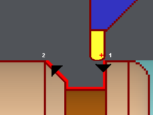
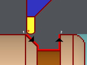
2 cutters compensation are used according to the sense of the profile.
The right point is piloted because the profile starts on the right. | The left point is piloted because the profile starts on the left. |
 |  |
2 points forced
2 cutter compensations are used, but you can choose the first pilot point.
Pilot Type | Left | Center | Right | Center P | ||||
Imaginary Point / Tool Center |  |  |  |  |  |  |  |  |
Pilot Type
Definition
This command is used to define the pilot points of the toolpath.
It depends on the chosen Number of pilot points.
Left: the compensation is taken into consideration on the left of the tool (columns with ‘Left’ on the above tables).
Center: the compensation is taken into consideration on the center of the tool (columns with ‘Center’ on the above tables).
Right: the compensation is taken into consideration on the right of the tool (columns with ‘Right’ on the above tables).
