
Cycle: Jig Boring, Drilling, Tapping, Counter boring, Reaming, Threading, Toolpath
Definition
|
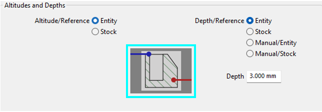
These two parameters allow to define the altitude and the depth from the geometric reference. There are eight possible cases, described below. |
|
|
|
|
The altitudes and depth pages in the holes cycles now feature new icons. |
|
|
Altitude/Ref: Entity 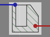
Depth/Ref: Entity |
Altitude is the Z of the entity and SD. Depth is the depth of the entity, if it has one. Otherwise, it functions the same as Entity+Manual/Entity. |
Altitude/Ref: Stock 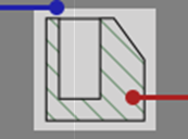
Depth/Ref: Entity |
Altitude is the Z of the stock and SD. Depth is the entity's depth, if it has one. Otherwise, it functions like Stock+Manual/Entity. |
|
Altitude/Ref: Entity 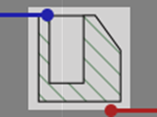
Depth/Ref: Stock |
Altitude is the Z of the entity and SD. Depth is a through hole. |
Altitude/Ref: Entity
Depth/Ref: Stock |
Altitude is the Z of the stock and SD. Depth is a through hole. |
|
Altitude/Ref: Entity 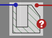
Depth/Ref: Manual/Entity |
Altitude is the Z of the entity and SD. Depth is the value defined in the Depth field, measured from the entity. |
Altitude/Ref: Stock 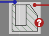
Depth/Ref: Manual/Entity |
Altitude is the Z of the stock and SD. Depth is the value defined in the Depth field, measured from the entity. |
|
Altitude/Ref: Entity 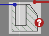
Depth/Ref: Manual/Stock |
Altitude is the Z of the entity and SD. Depth is the value defined in the Depth field, measured from the stock. Used for centering. |
Altitude/Ref: Stock 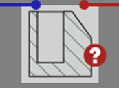
Depth/Ref: Manual/Stock |
Altitude is the Z of the stock and SD. Depth is the value defined in the Depth field, measured from the stock. Used for centering. |
|
|
The parameter Depth enables to define the depth retraction from the reference. This parameter can be modified only if Entity, Stock or Manual/Stock is selected in Depth/Reference. This value can be positive or negative. |
Special Feature
If Altitude/Ref and Depth/Ref are both set to stock, there are a few features to consider:
-
The Rapid plane alt. value is still defined with respect to the origin of the stock.
-
However, the Safety distance is now dynamically related to the stock; the computation takes into consideration any pre-processing on the stock.
|
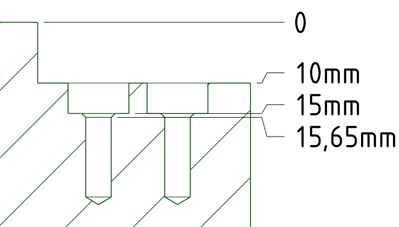
For instance, let’s consider this image. The Rapid plane alt. is set to 15 mm and the Safety distance is 2 mm. The safety distance for the drilling cycles is lower than that of the stock. |
|
The resulting processing of the drilling cycles is as per below:
|
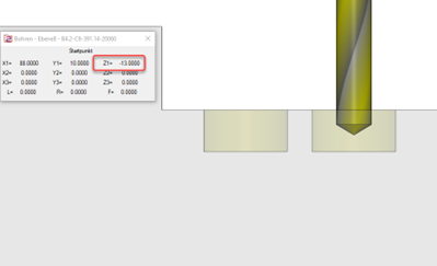
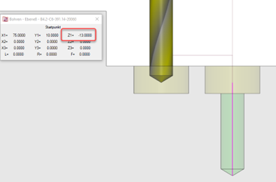
Pre-positioning to the Rapid plane alt. of the stock at Z15. G00, G90, G54, X88. Y10. G43 H... Z15. |
||
|
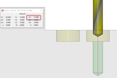
Motion to the Safety distance Z -13 in the counterbore - 2mm above the drill operation followed by the drilling process with subsequent retraction to that safety distance. G99, G81, Z-30. R-13. F... |
|
|
|
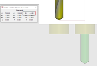
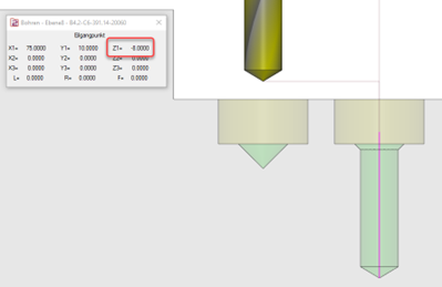
Retraction to safety distance Z -8 just above the stock (2mm above the level of the bore) between the drill cycles to position for the next operation. G80 Z-8.X75. |
|
|
|
Repetition of drilling cycles G81 Z-30. R-13. F... |
|
|
|
At the end of the drill operation, the tool retracts to the Rapid plane alt. level at Z 15 G80 Z15. |
||
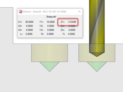
For the case where a chamfer is defined and pre-machined for the counterbore, the calculation of the safety distance takes into account the chamfer resulting in the safety distance for the drill being slightly deeper. For instance at Z -13.65 rather than Z -13 in the example. The switch between the drilling cycles are still carried out at Z -8, hence a safe flow is guaranteed.
|
|
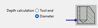
Depth Calculation
Cycle: Reaming
|
|
The depth calculation parameter for tool end or diameter is included in the reaming cycle, as we can set the chamfer for the reaming tool. |
|