
Cycle: Chamfering
Description
It refers to the calculation of chamfer size is determined by the following parameters:
Chamfering Strategy
|
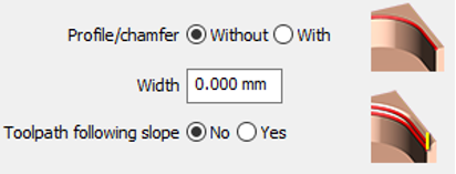
In most cases where no chamfer is designed on the solid or profile (Profile/chamfer is set to Without). The size of the chamfer on the XY plane is determined by the parameter Width. If the chamfer is already designed, the Width parameter is obsolete (Profile/chamfer is set to With) and the size is automatically read on the solid. For information about Toolpath following slope, click here. |
|
Depth Recalculation
|
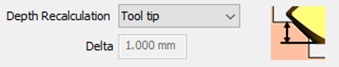
Depth Recalculation parameter provides the ability to adjust the depth of the tool tip. It is recommended to have the tool with Z depth more than the actual Z value of the chamfer. This will ensure there is no burrs/ridges left after machining. |
|
Four possibilities are available:
|
Tool tip |
In this case, the bottom Z value needs to be defined. If the value set is the same as the chamfer size, the tool tip will be the same level as the bottom edge of the chamfer. It is recommended to set the Z value greater. |
|
|
Piloted Point |
Similar to tool tip. The only difference is the offset of the tool depending on the location of the pilot point. |
|
|
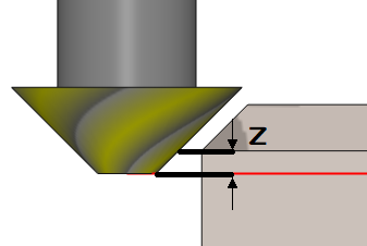
Z Delta |
In this mode, the Z altitude (Bottom Z) value for the chamfer does not need to be defined during geometry selection. In the strategy page, a delta value can be defined which will offset the tool tip in the Z direction from the edge of the chamfer. |
|
|
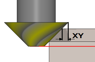
XY Delta |
This mode is similar to the Z Delta, except that the Delta value offsets the edge of the tool to the top edge of the chamfer. |
|
|
▶️ Watch a video explaining the strategies. 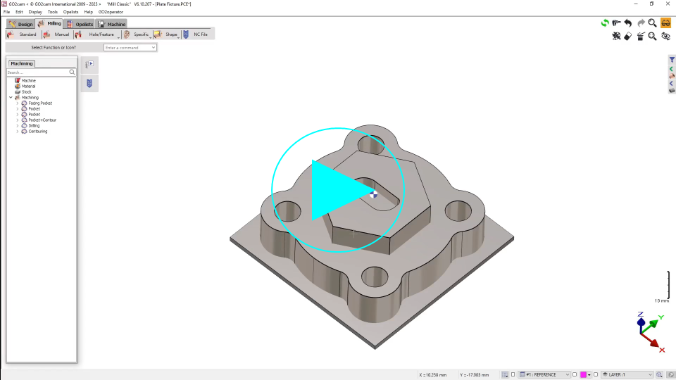
|
The same principle applies for chamfer from the back.
|
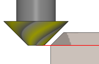
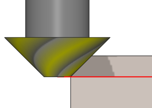
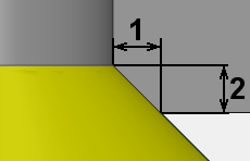
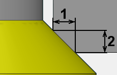
#1 on the images is the width in XY Plane of the chamfer and #2 is the Z value. Having the Z value on the same level as the chamfer edge can lead to shank collision as on the image on the left. It is advised to always offset the Z value to avoid this as shown on the image on the right. |
|
|
|