
Cycle: Deep Drill, Clevis
Definition
The behavior of the clevis mode is explained below.
|
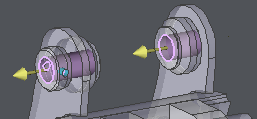
The purpose of the machining is to accelerate the motions between two or more coaxial holes.
In Clevis mode, most of the parameters are not accessible. The only important parameter to define is the value of the feedrate between the machined holes. This parameter is located in the Technology page. |
|
To use the clevis mode, the holes machined must be unified in one and only hole entity.
There are two ways of working:
-
if HMF extra module is not available, use the standard holes function.
-
if HMF is available, recover the shapes and unify holes together.
|
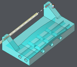
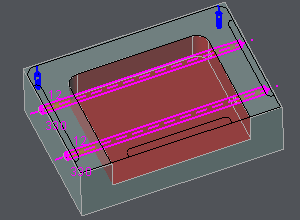
1. The following process either on 2D geometry or solid also cab be used. What is required to be done is to create a unique hole with the total length of the several holes to be machined. For the example on the right, there are two times two coaxial holes, each hole is 50 mm long but the total length is 330 mm. Then, create one hole with 330 mm long. Due to the stock management, if the pocket is machined before the holes, then the clevis mode is applied. The feedrate is higher inside the pocket. |
|
|
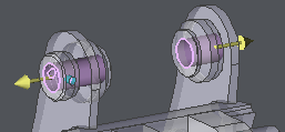
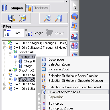
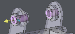
2. In case the Holes Machining Features (HMF) module is available, the Holes Recognition Function can be used. This command can be found in Design / Solid / Operations on Solid and in the Interfaces, in Solid / Geometrical Calculation. Before unifying the holes, check that the direction of Z are the same. If not, select the hole to invert, and click Invert command on the bottom of dialog. After this, select the holes to unify in the tree with Ctrl key for multiple selection. Then do a right-click, choose Union of selected holes. |
|