
From V6.12, there are 2 methods to create and machine into a developed plane:
-
Manual creation of developed plane and apply the machining cycle
-
In Turning, new command to create and machine into a developed plane in 1 step
1. Manual Creation
Creation of Developed Plane
|
▶️ Please read the explanation below and also note that you can watch tutorial videos at the bottom of page. |

|
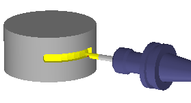
Creation of a plane developed around one axis. Choose the distance (diameter of the cylinder) and the axis of rotation. Once the plane is created, you can use any wireframe command to draw geometry inside this plane. It will wrap the geometry around the cylinder. Then you can program 2 axis machining that will be wrapped around the shape. |
|
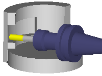
During machining, you can select the Z orientation of the tool. There are two options:
|
|
|
|
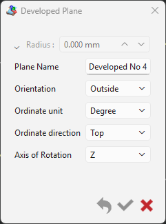
A new dialog box now enables the creation of advanced planes using the same settings available in the ribbon. Diameter/Radius: Specify the diameter for the unfold area. For a simple cylindrical unwinding, you can enter the diameter directly in this field. Orientation: Select how the unwinding plane is positioned; this choice determines whether machining will occur on the exterior or for large turned components, possibly with an angle head on the interior surface. Ordinate Unit: Choose between a degrees unit or mm (or inches). This setting defines the unit for the vertical (Y or C) axis on the unfold plane. Ordinate Direction: Indicate the direction of the '+' sign, either pointing Top or Bottom |
|
|
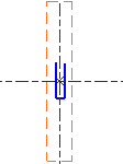
Bottom Ordinate Direction 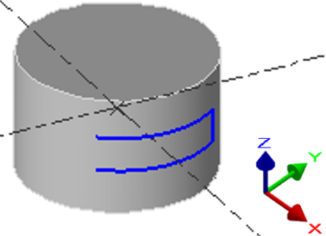
|
Top Ordinate Direction 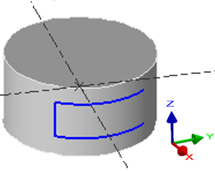
|
Design or project geometry
When the plane is created, you can draw in this plane, or import geometry designed in another plane.
You cannot change the view in a developed plane: only top view is available!
|
|
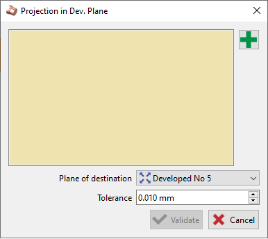
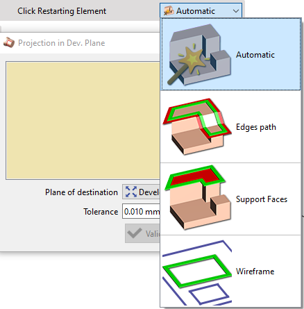
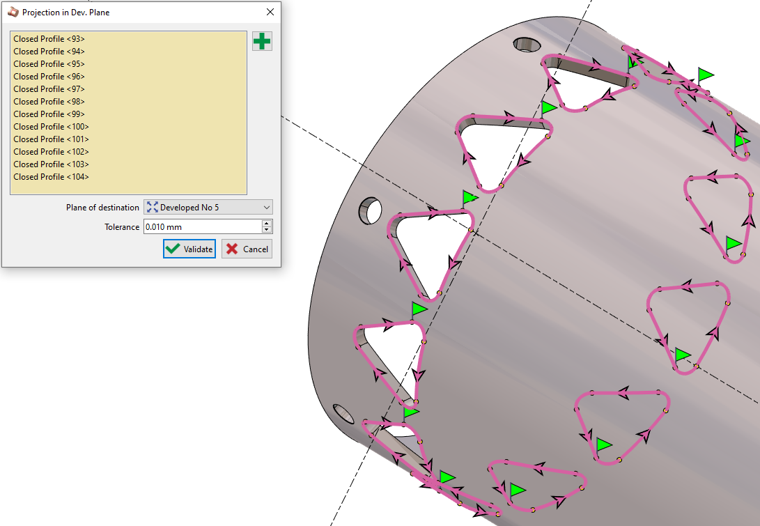
The import is done by projection with the command Projection in developed plane available in the menu Workplane. In the command Projection, 4 modes of profile creation are available; Automatic, Edges path, Support faces and Wireframe. |
|
A dialog window opens on selecting Projection in developed plane.
|
|
|
Clicking on the green + Icon will give us access to choose the mode of profile creation: Automatic lets the software choose the optimum method to select the profiles. Edges Path allows the selection of the edges of a solid directly, without recovering 2D geometry beforehand. Support Faces provides the ability to simply click on a face to select multiple profiles. Wireframe allows to select any drawn or existing wireframe on the solid. |
|
|
Upon multiple selection of profiles, continuity is applied on elements on position 0° and 180°. Also holes are not taken into consideration. The user also now has the possibility to manually add or remove any profile from the window. |
|
|
▶️ Watch a video demonstrating the various features added for Developed Plane. |

|
The elements projected into a developed plane are not anymore transformed into polygons. They are kept as arcs and segments, for a better machining result.
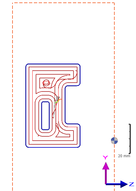
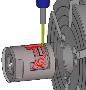
Program a cycle in Developed Plane
|
Once the workplane is created, this is very simple: proceed as you do usually with any other shape. Just check that you are currently working in the developed plane. You can program any 2 axis operations, as we show you in the example with a pocket. |
|
|
|
▶️ You can watch a video on how to project profiles and machine them in developed plane: 
|
▶️ Here is a video where we wrap a text on a cylinder then program a Marking operation in a Developed Plane: 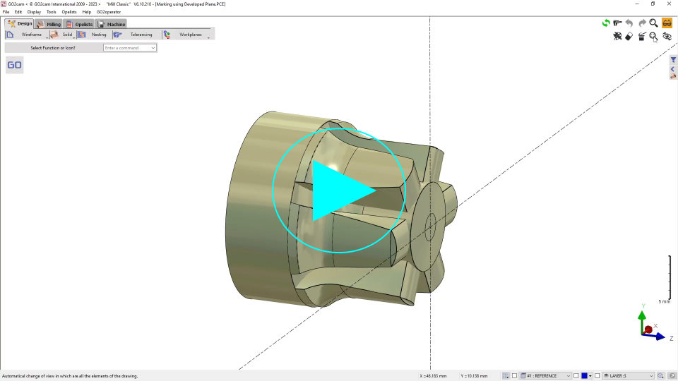
|
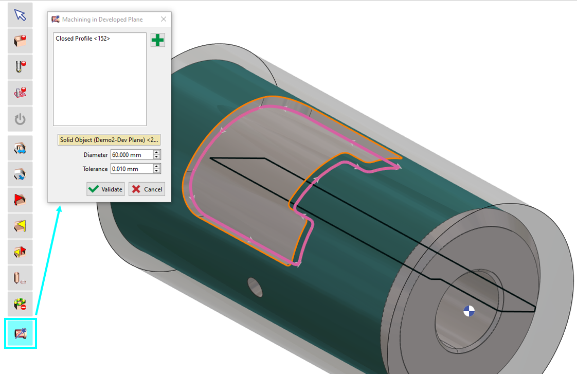
2. Machining in Developed Plane
|
|
You can utilize the developed plane function when selecting geometry for machining. Upon clicking the geometry selection option, an icon representing the developed plane machining will be visible. Select the desired profile to be machined in the developed plane. For the diameter, you can either manually input the value or select your solid, and the diameter will be automatically filled. Once validated, proceed to choose the appropriate tool and machining cycle. |
|

|
||