Skip table of contents

Exporting to Partners Software

GO2cam Vericut Export

To export data from GO2cam to Vericut for simulation, navigate to Tools > Standard Macros > Vericut.ppi. This interface will export all necessary items for Vericut to simulate machining.

  • For milling projects: A Vericut project containing machine and parameter settings is required.

  • If no project is provided: You'll need to manually create one within Vericut.

Interface Options:

DialogBox-20170120-102439.png
  • Exchange directory: Specifies the folder where Vericut files will be exported.

  • Export model: Exports an STL file of the solid part.

  • Export stock: Exports an STL file of the stock.

  • Export clamps: Exports all tooling systems as STL files.

  • Running PP: Automatically launches the post processor to generate an NC file after export. If unchecked, the NC file will be recovered.

  • Vericut reference project: The Vericut project to be filled with exported items.

  • Model file, Stock file, Tools file: Names of the corresponding files.

  • Generate NC file / Recover NC file: The name of the NC file to be generated or recovered, depending on the "Running PP" setting.

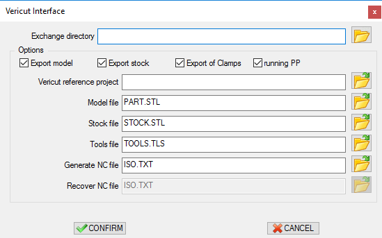
In summary, the Vericut.ppi interface provides a streamlined way to transfer data from GO2cam to Vericut for simulation, offering flexibility in terms of project setup and file export options.

image-20240911-064912.png You can find the Vericut export process explained in detail in this video.

Vericut Export.png

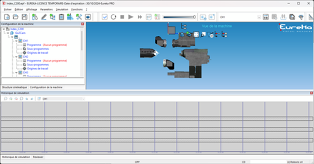
GO2cam Eureka Export

Exporting from GO2cam to Eureka for Simulation

To export a project from GO2cam to Eureka for simulation:

image-20240911-055419.png
  1. Ensure the script template folder contains the machine definition.

image-20240911-055447.png
  1. Copy necessary files to the GO2cam Exchange directory. The .emsf file is a template that will be modified based on the part being machined.

  2. Open the .epf file in Eureka. This will load the machine definition.

image-20240911-055521.png
  1. Click on the "GO2cam" submenu and select "Load configuration." This will load tools (.etf file) and STL files created by GO2cam for the stock, part, and other components.

  1. View or modify tools: Click on the icon surrounded in red to access tool parameters. These values correspond to those in the .etf file.

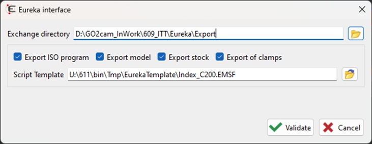
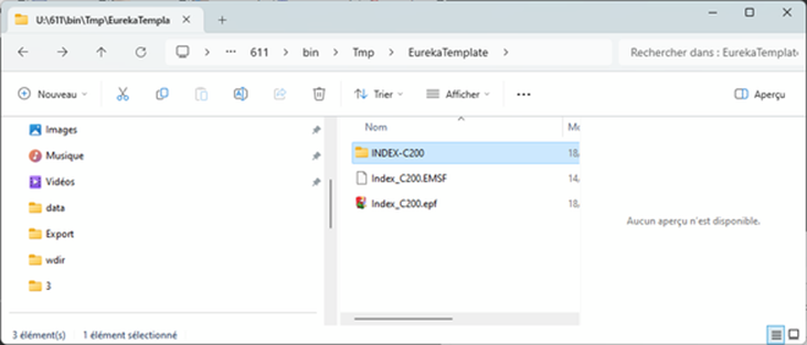
Note: The "LoadEurekaEtfFile.js" script (located in U:\New\3d\usi\vericut) can be used to load the .etf file into GO2cam. However, it may fail if the file contains non-ASCII characters. Eureka requires ASCII encoding, not UTF-8.

JavaScript errors detected

Please note, these errors can depend on your browser setup.

If this problem persists, please contact our support.