
This environment is dedicated to the drafting and the dimensioning of the part. The commands are sorted in two menus:
-
Layout Design: this menu enables to define the layout of the current part.
-
Creation of Title Block: menu dedicated to the creation and definition of title blocks.


|
|
|
Presentation
Below is a layout defined in GO2cam with some of the functionalities of the Layout Drafting module:
-
Texts (such as ‘Chamfers with no dimension: 1 x 1’)
-
Dimensions (linear and axial dimensions)
-
Annotations (such as ‘4x Drilling d5 x 20’)
-
Tolerances (shape, orientation, position and run-out tolerances)
-
Images (import of the logo)
-
Title Block (creation and settings)
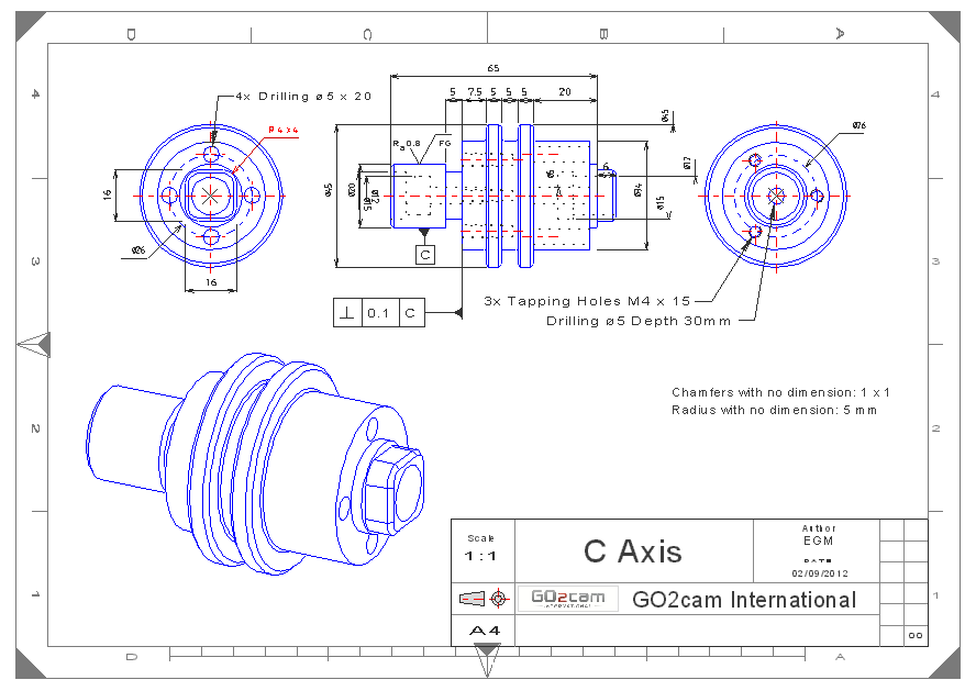
Layout of Wireframe Geometry
|
In this video:
|
|
|
Linear Dimensioning
|
|
|
Circular Dimensioning
|
|
|
Point Dimension When using this command, you first need to show the origin of dimensioning, a point that will be the 0,0. The 2nd video details some options:
|
|
|
Chamfer Dimensioning Two ways to define chamfer dimensions. |
|
|
Angular Dimensioning |
|
|
Dimensioning Alignment The process needs to start by choosing a dimension that will be the reference for alignment. A shortcut for this command is available in the popup menu. |
This video shows how to align various dimensions in a layout in GO2cam. 
|
|
The Popup menu on dimensions opens several interesting options:
|
|
|
Dimensioning a hole This video shows how to modify the dimension of a hole with threading and how to include tolerance values in dimensions. |
|
Layout of Solid Geometry
|
Creation of layout for Solid:
|
|
|
Direct dimensioning of a Solid
This video shows how to insert dimensions by clicking directly the edges of a solid. |
|
|
Detail view |
|
Complementary Options
|
Print Layout to PDF We show you how to generate the PDF file from a designed layout in GO2cam, by using the command Print.
|
|
|
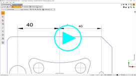
Saving user preferences You can create your own customized styles for dimensions, save them and use it when you need. |
|
Creation and Use of Title block
|
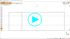
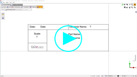
Title Box Creation |
|
|
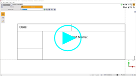
Text Creation |
|
|
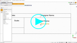
Questions Creation
|
|
|
Image Insert Images can be drag and drop and converted in polyhedron. |
|
|
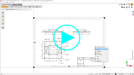
Use of Created Title Block |
|
|
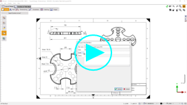
How to fill the Title Box |
|