
Cycle: Contouring, Contour rework, Slotting, Chamfering, Taper cutting, Profile cutting, Chamfering
|
|
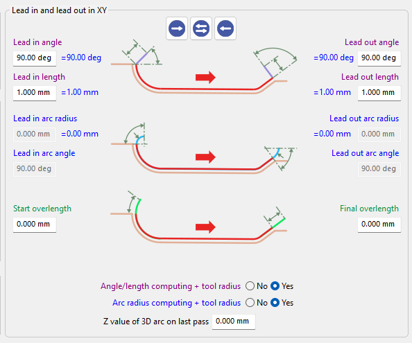
Learn more about the interface for the Lead in/Lead out parameters, by clicking the link here. |
|
Overview
Lead in/Lead out angle and length parameters define how the tool approaches the machining path before engaging in cutting.
These settings control the direction and distance of the tool movement as it transitions from rapid positioning to the programmed toolpath.
Proper adjustment of these parameters ensures a smooth entry into the cut while minimizing abrupt tool engagement.
|
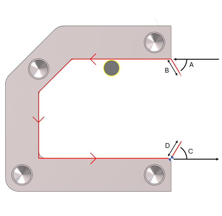
A. Lead in Angle
The Lead in angle, together with the Lead in length, defines the tool’s entry movement at feed rate before the machining path begins. This movement allows the tool to progressively engage the material and apply tool diameter compensation (G41/G42). The angle can be set between 0° and 90°. It is defined as an absolute value relative to the profile, depending on the toolpath position and offset configuration. |
B. Lead in Length
The Lead in length defines the distance of the tool entry movement before reaching the machining path. This value must be greater than the tool radius to ensure proper application of tool diameter compensation. The length is measured along the Lead in angle direction, not along the X or Y axes. |
C. Lead out Angle
The Lead out angle, together with the Lead out length, defines the tool’s exit movement at feed rate after the machining path. This movement allows the tool diameter compensation (G41/G42) to be cancelled smoothly. The angle can be set between 0° and 90° and is defined as an absolute value relative to the profile, depending on the toolpath position and offset configuration. |
D. Lead out Length
The Lead out length defines the distance of the tool exit movement after leaving the machining path. This value must be greater than the tool radius to ensure proper cancellation of tool diameter compensation. The length is measured along the Lead out angle direction, not along the X or Y axes. |
|
▶️ Watch a video on Lead in/Lead out : Angle and length. 
|