
Cycle: millyuGO pocket, Facing Pocket, Pocket, Pocket+Contour, Pocket rework, Finish Contour, Finish Reworking, millyuGO, PAM, Facing Roughing, Pocket - Face, Flat Face Finish, Finish Contour -Shape, Plunge Pocketing, Plunge Contouring
Definition for Standard Cycles
When the toolpath is not continuous, GO2cam offers several possibilities to manage the motions between the passes. The motions in rapid or Fmax feedrate or a ratio of rapid feedrate can be defined. Here are the parameters to adjust:
Motions

|

|
Rapid: rapid motions are done. |
|

|

|
G1 Fmax: the motions are done with Fmax value, which is defined in the machine file. |
|

|

|
G0/G1 Fmax: we modulate the feedrate according to the parameter Rapid/Fmax %. |
Fmax safety distance
The Fmax safety distance defines the clearance height used when the tool retracts before a repositioning move at Fmax. It provides a safe separation from the part or stock, helping prevent collisions while keeping non-cutting movements as short as possible.
We will use the term SD as an acronym for safety distance on this page.
Rapid/Fmax %
See also: millyuGO — Detailed Behavior of Retracts below for a full worked example across the whole threshold range.
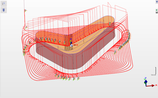
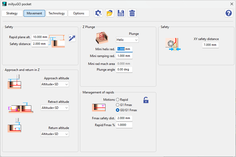
Since V6.09.209, the behavior of the millyuGO cycle has improved so that the user can better control the tool's behavior when repositioning. This means the user can now specify a percentage value (the Rapid/Fmax % threshold described above) from which the withdrawal to the safety distance, should take place. The examples below illustrate this pattern of behavior, from a threshold of 100% (systematic retract to SD) down to 0% (retract to SD only when strictly necessary).
millyuGO G0/G1 — Rapid traverse threshold = 100%
|
Diagram |
Movement Parameters |
|
|
-
The tool always moves to SD, i.e. identical to the Rapid traverse option to SD.
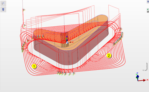
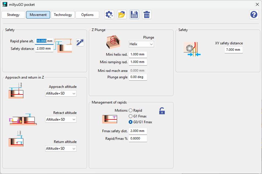
millyuGO G0/G1 — Rapid traverse threshold = 80%
|
Diagram |
Movement Parameters |
|
|
-
Here, the retreats to SD continue to dominate, but the first repositioning can be seen with the take-off distance (1)(2).
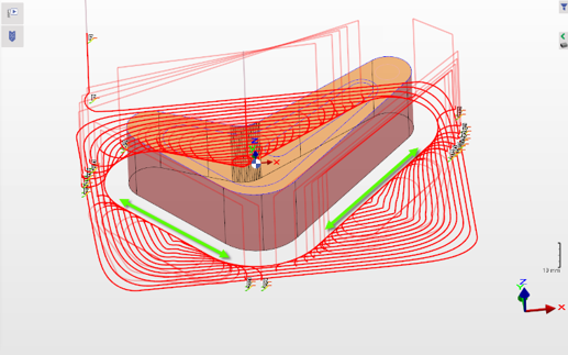
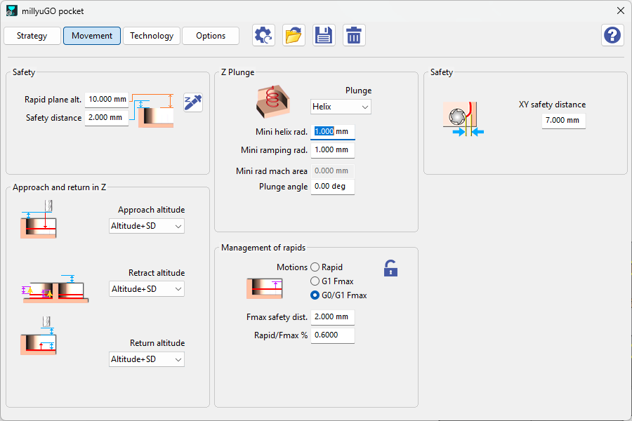
millyuGO G0/G1 — Rapid traverse threshold = 60%
|
Diagram |
Movement Parameters |
|
|
-
The range of repositioning with the lift-off distance increases.
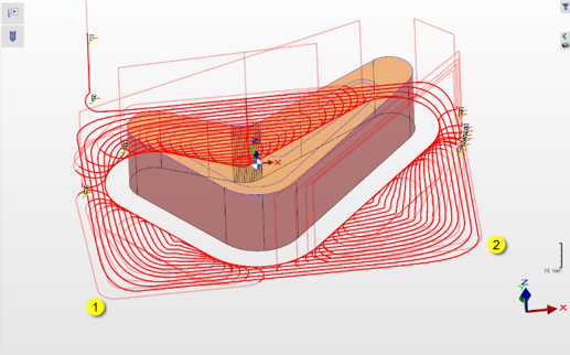
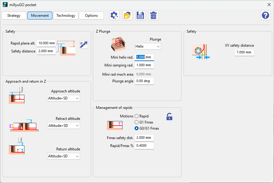
millyuGO G0/G1 — Rapid traverse threshold = 40%
|
Diagram |
Movement Parameters |
|
|
-
Now the repositioning to the lift-off distance dominates, and undesirable long movements around the component can occur.
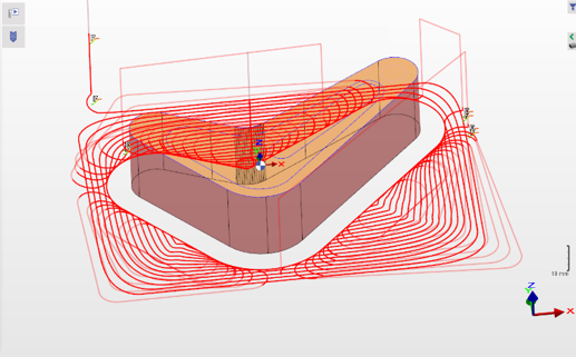
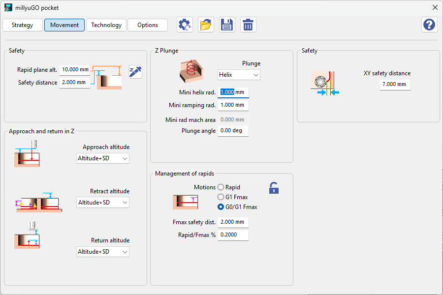
millyuGO G0/G1 — Rapid traverse threshold = 20%
|
Diagram |
Movement Parameters |
|
|
-
Even fewer withdrawals on SD.
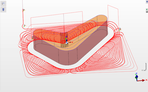
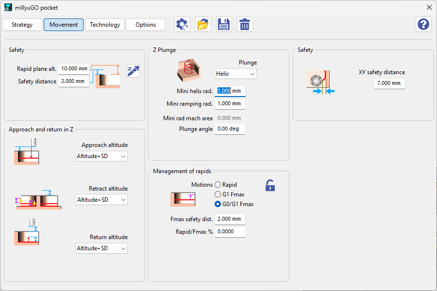
millyuGO G0/G1 — Rapid traverse threshold = 0%
|
Diagram |
Movement Parameters |
|
|
-
Only absolutely necessary withdrawals to SD will be carried out.
Cycle: Plunge Pocketing, Plunge Contouring
Definition for Plunge Pocketing, Plunge Contouring
Management of the rapid motions between XY passes and definition of the feedrate values. The feedrate values which will be taken are defined in the page 'Technology'. The Fmax value is defined in the machine file. It can be defined in the tab 'General'.
In the strategy, there are three options:
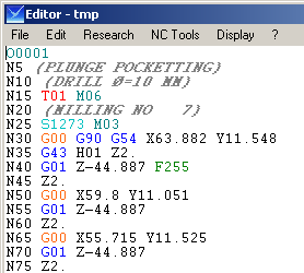
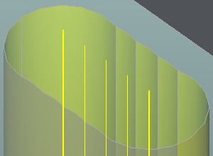
Rapid
|
|
There is no path displayed on GO2cam's screen. |
|
G00 programs each motion between two passes. |
|
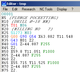
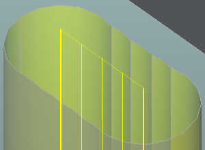
G1 Fmax
|
|
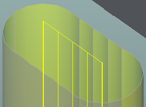
The path displayed is transparent. |
|
G01 programs each motion between two passes. The machine file defines Fmax as F1000. |
|
G1 feedrate
|
|
The path displayed is full. |
|
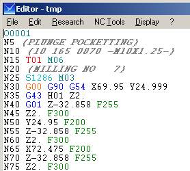
G01 programs each motion between two passes. Feedrate values are read on the 'Technology' page of the cycle. Use the return (Z) and retract (XY) feedrate —F300 and F200 in our example. Use the general feedrate for each G1 motion (F255 here). Set return and retract feedrate to 0 for this. |
|