
GO2cam Production works with solid models whereas GO2cam Dental works with mesh.
Previously, the GO2cam software was able to read and open mesh components but couldn’t be edited or used for programming purpose.
In order to homogenize the management of mesh components between GO2cam Production and GO2cam Dental as well as standardize the management of Mesh and Solid in GO2cam Production, mesh modelling and computation has been included in the software as from version V6.12.
Presentation
This new menu gives you the possibility to draw mesh entities.
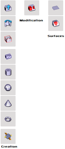
Mesh Creation
Similarities with Solid
|
Topics |
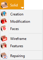
Solid Menu |
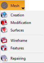
Mesh Menu |
||
|
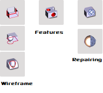
The main menu for Mesh mirrors that for the Solid. Faces has been changed to Surfaces due to the fact that Mesh works on surface-based modelling. |
|
|
||
|
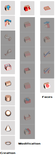
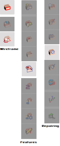
The commands are similar for Mesh. However the commands that are unusable for mesh have been removed as shown on the images on the right by the darkened icons. |
|
|
|
|
Main Key Points of Mesh Modelling
|
CAD Import |
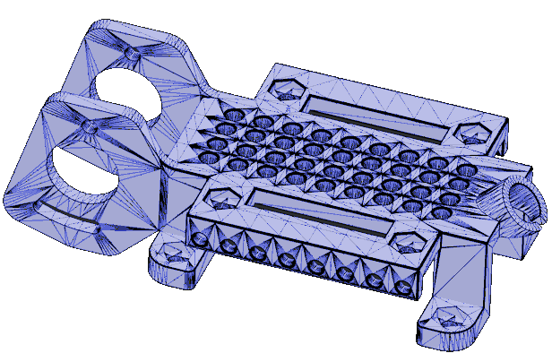
Mesh models can be imported and positioned with the same methods as solids. Flatness can be recognized in the mesh! |
|
|
Workplanes |
Planes can be created on a mesh model: the plane is not created according to the clicked triangle but by propagation on the shape. |
|
|
Stock Creation |
A mesh model can be selected as the stock |
|
|
Holes |
Holes recognition can be applied on a mesh model; after that you can drill those holes! With mesh design you can then create ‘stop faces’ to avoid machining the holes. |
|
|
5X Simultaneous Milling |
A new 5 axis operations is available.. |
|
|

|