
Cycle: Threading (Turning)
The ISO Metric Thread Profiles
|
The ISO profile for threads (metric) is referenced from the Standard NF ISO 68. The profile is obtained by cutting the screw or nut with a plane passing through the axis. See the image on the right for reference. The profile in Blue designates the Nut. The profile in Yellow designates the Screw.
|
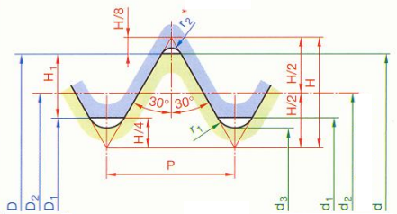
D, D1, D2 are the diameters of the Nut d, d1, d2, d3 are the diameters of the Screw. |
||
|
d=D= Nominal Diameter |
d2=D2= d - 0.6495P |
P = Pitch |
H1 = 0.5412P |
|
d1=D1= d - 1.0825P |
d3= d- 1.2268P |
H = 0.866P |
r1 = 0.1443P |
Pitch and Passes parameters
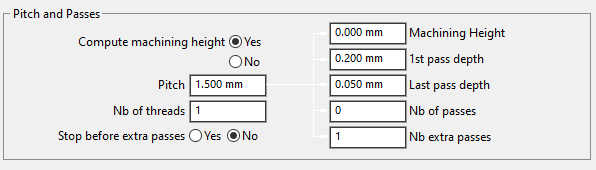
The options for Pitch and Passes allow you to configure different parameters for the threading operations.
|
Calculate machining height |
Yes or No |
|
Pitch |
Thread pitch or offset between 2 successive plunging. |
|
Stop before extra passes |
Creation of a stop before calling the extra passes. |
|
Machining height |
Machining height |
|
1st pass depth |
Incremental depth corresponding to pass cutting |
|
Last pass depth |
Machining’s last pass depth (decreasing passes). |
|
Nb of passes |
Allows to check the number of passes. |
|
Nb extra passes |
Number of spring passes at the end of machining. |
Calculations of the various threading parameters is automatically done in GO2cam based on the standard.
When changing the pitch parameter, the Machining Depth and Nb of passes changes depending on the type of insert used for the operation and the ISO standard.
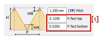
In the tool window above, we defined the pitch and the factors [1] (Top and bottom) to determine the total thickness between the outer pass and the inner pass.
The machining pass must take into account the H/8 and H/4 positions. It is this calculation that justifies the difference.
|
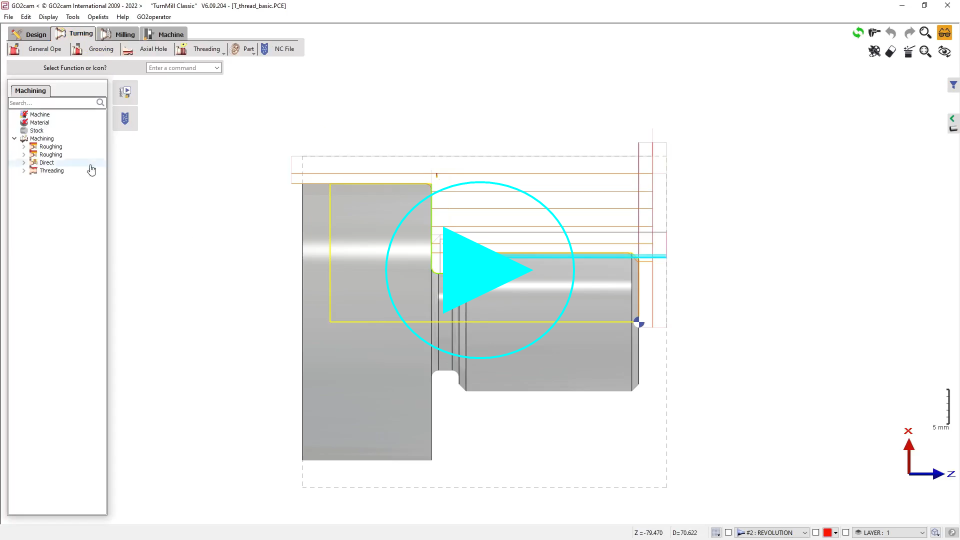
▶️ You can watch a video on calculation of depth of thread in turning:
|