
Cycle: Slotting
Overview
GO2cam provides several methods for machining slots, allowing the strategy to adapt to the available geometry. By selecting the appropriate Profile Selected option and defining the Slot Width when required, slots of various shapes and configurations can be programmed efficiently. The following examples illustrate the most common slot machining methods and the settings used for each strategy.
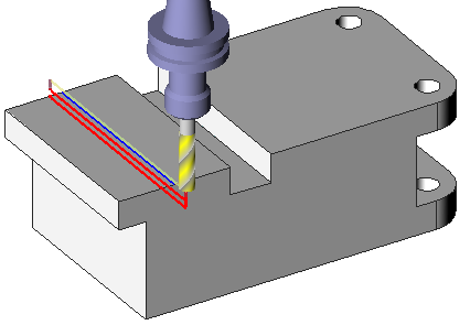
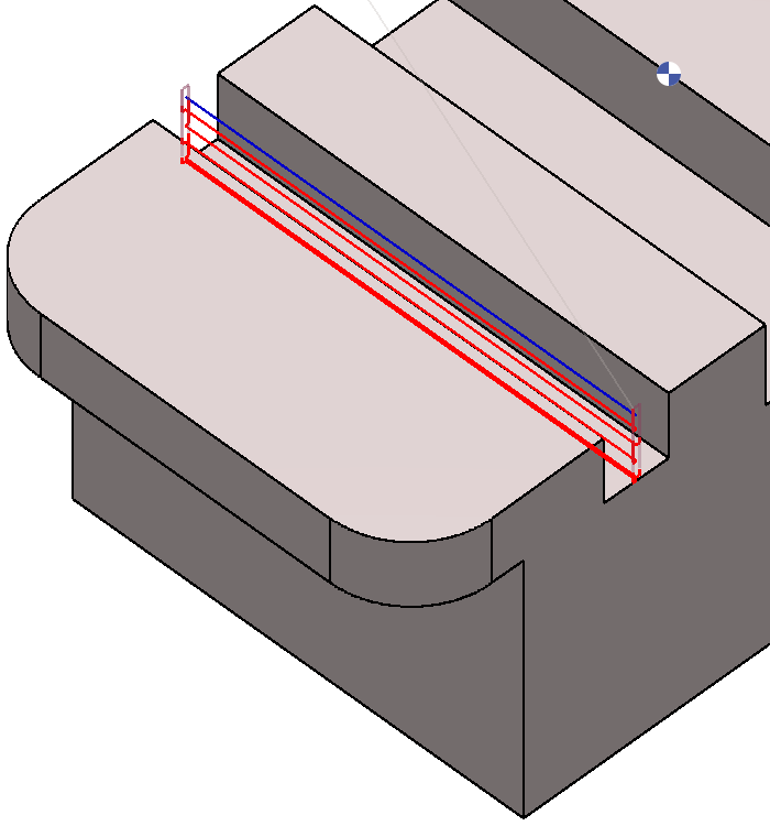
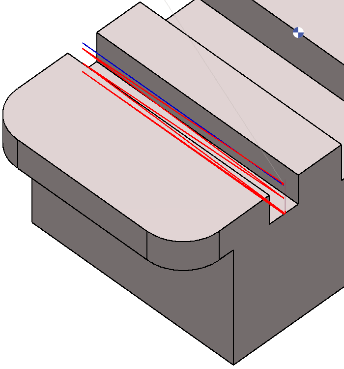
Slotting Center one path
|
The slot is not designed in solid, there is one segment in center of slot:
|
|
||
|
|
|
|
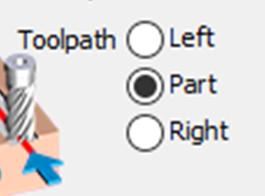
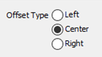
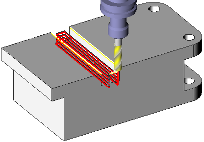
Toolpath Option
|
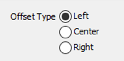
This setting is activated only when the Centre option is selected in the Offset Type field, providing access to the following options. |
||

|
|
|
|
▶️ Watch a video on Slotting center one Path. 
|
||
Slotting Side
|
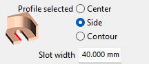
There is no center, only the side of the slot. Simply select the segment and define the following settings:
|
|
|
|
|
|
|
▶️ Watch a video on Slotting Side. 
|
||
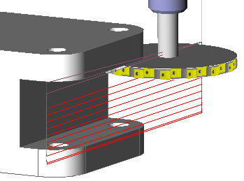
Slotting Top and Bottom
|
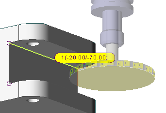
In this case both the Toolpath and Offset type have been set to Left. The selection of the profile is done directly on the solid. Choose the altitude also by clicking the solid (-20 and -70). In strategy, select two piloted points. |
|
|
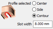
Slot width = 0 because we select directly the bottom of slot. |
|
|
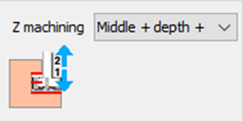
With the Z machining set to ‘Middle – depth + alt’, define the process:
|
|
This behavior can be checked in the simulation. |
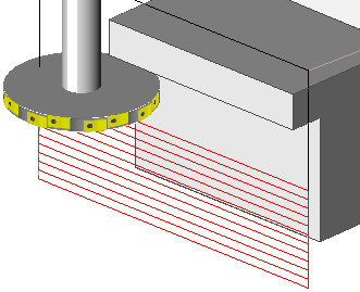
Slotting Top
|
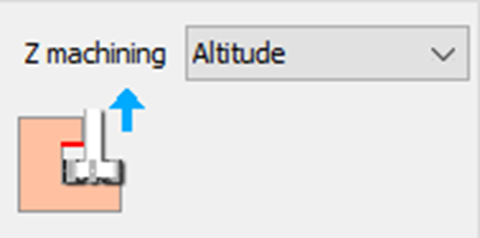
The case is very similar to previous example: the difference is the management of Z machining. Choose Altitude and define the altitude of the top by clicking the solid directly. |
|
|
|
▶️ Watch a video on Slotting Top and Bottom. 
|
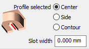
Slotting Contour
|
The case is similar to Slotting Centre one path. However here, the selection can be done directly by selecting the bottom or the contour profile. This allows to make a slot whose width is the side of tool Choose “Profile selected: Contour” for this strategy. |
|