
A basic workflow to program a robot in GO2CAM is as such:
Robot Module
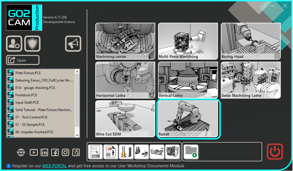
The robot interface may look similar to the MTE environment, however, it is its own separate module. Available from the homepage if you purchase the package, a robot file can only be opened in this module. |
|
CAM programming of a part
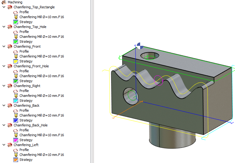
This part of the process is similar to the programming in the Machining center module. Import the part. Define the cycles; geometry selection, tool selection and cycle selection as usual. The robot is considered as a milling machine, so any milling cycles can be used for robotic machining, from standard, 3X to advanced 5X. Calculate and simulate the motion of the tool. Several Approach and Return points can be defined in the geometry selection process to manually control the approach and return toolpath with the part. |
|
Robot Configuration
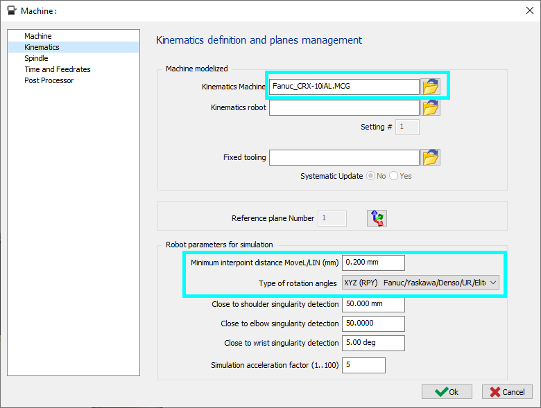
Robot kinematics Once one or mores cycles are created and calculated without error, select a robot which will drive the selected tool to execute the machining cycles. In the Machining tree right-click on Machine then select Edit. The machine dialog will open. Choose a Robot .MCG file for the Kinematics Machine, define the parameters and click on OK to validate. If a robotic cell is to be defined, 2 .MCG files are to be set. Kinematics robot should be a standalone robot while the Kinematics Machine can be other parts of the cell. In such a case, it is not possible to jog the robot’s axis position. It’s recommended to work with only one MCG to have full access to all the robot’s components. Minimum interpoint distance MoveL/LIN (mm) : This is the minimal distance for a linear movement for the robot program generation, this can be useful for curve path without need of high precision by making the path movement quicker with less points (the simulation will not be affected by this parameter). The Type of rotation angles can be set based on the robot make being used. Threshold values can be set for singularity detection for the shoulder, elbow and wrist joint. The robot can be visualized with the part by going to the Machine menu and selecting the Tooling submenu. The robot may be hidden by middle-clicking on the robot name in the tree. This is useful in case the part is hidden by the robot body. For details on additional parameters for tooling and simulation setup, click this link. |
|
Tool and Part Configuration
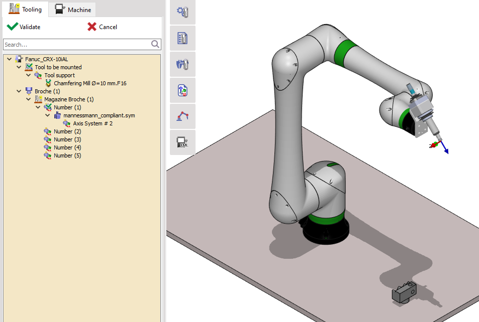
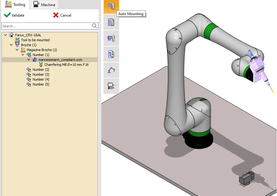
Loading the tools and toolholders is a similar process to MTE. Click on Auto-mounting to mount the tool on to the robot. Right click on the tool or the robot end axis to insert a toolholder. The tool can be further configured in the Tooling tab and the part can be repositioned in the Machine tab.
|
|
|
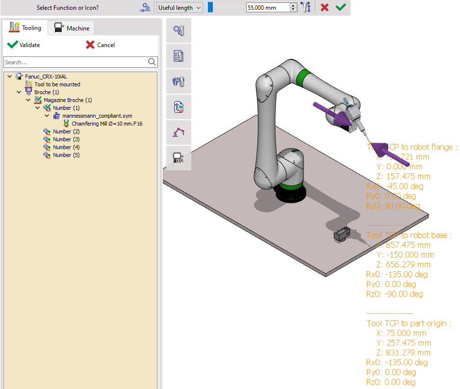
Tool By double-clicking on the tool either in the tree or on the program window, the Tool Centre Point (TCP) with respect to the robot flange is shown, you can also modify the tool useful length on the upper ribbon.
The TCP is expressed in X, Y, Z, Rx0, Ry0, Rz0.
|
|
|
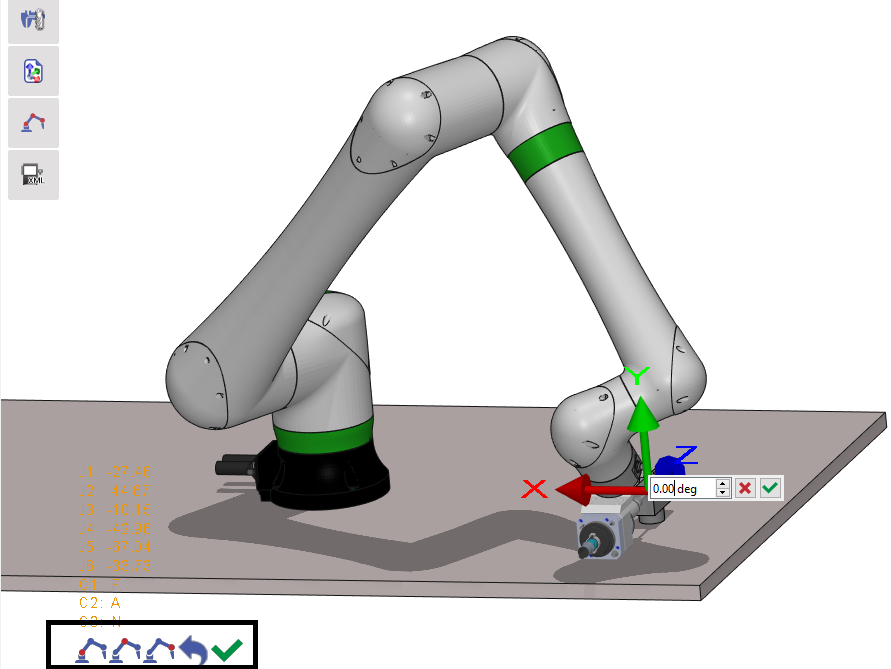
Part Reachability Initially, the position of the part may be too close or to far for the robot. The reachability of the part for the robot can be estimated. While in the Tooling tab, double-click on a point of the part, if this point is reachable the robot will be moved to touch this point with it’s tool or it’s flange point perpendicular to this point, else a message will show. To show the tool frame axes and move the tool, double-click on the robot and select a tool by clicking it (one robot may have multiples tools at the same time). Change the robot configuration while keeping the same tool position with the three icons on the lower-left. It is also possible to move the frame by left-clicking and dragging on the axis arrow for translation and rotation, or by right-clicking on the axis to specify a translation or rotation value. |
|
|
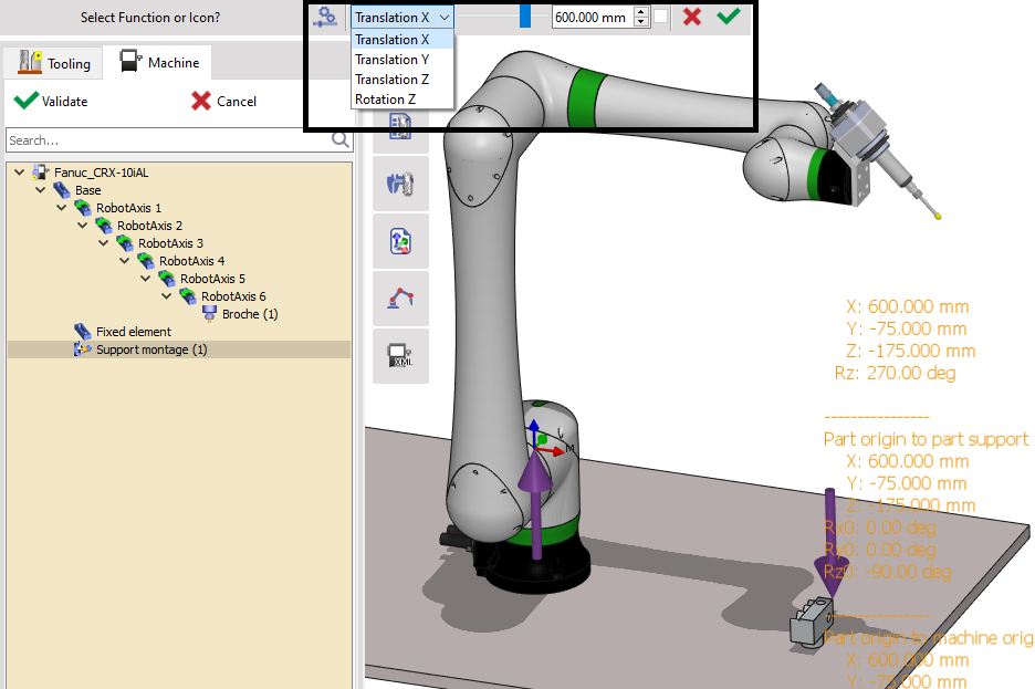
Part Repositioning The part can be repositioned with respect to the robot. Switch to the Machine tab, double-click on the work assembly support (renamed Support montage in this example). The cartesian position of the part will be visible in the robot’s base frame Reposition the part along X, Y, Z direction and rotation around only Z with the functions on the ribbon Validate the modification.
|
|
|
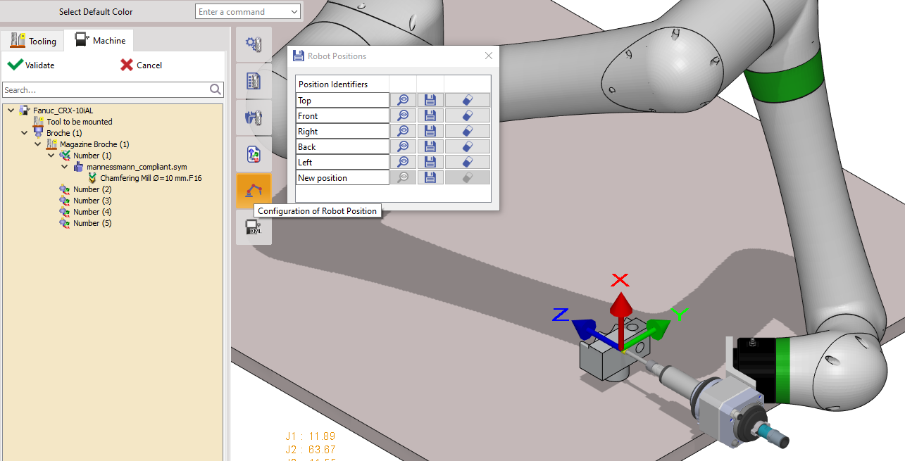
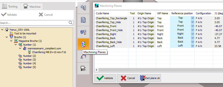
Reference position for each cycle Since the positioning of the robot through Cartesian point is redundant, the configuration or orientation of one cycle on a plane may not be suitable for another cycle on another plane, it’s better to define a reference position for each cycle. In fact, to generate the joint position path of each cycle, a reference position is necessary. During the whole path for this cycle, the same configuration of the reference position is kept and the orientation is referenced. If you want to learn more about it, click here: Robot Reference Position Creation. To add new or modify existing reference position, click on the Configuration of Robot Position command on the left toolbar. Position the robot to a face based on the plane. Change the orientation by dragging the tool TCP axes to attain a suitable positioning of the robot on the face Save the configuration with the save icon for the respective planes. Once all the necessary reference positions are created and saved, they need to be associated with the defined cycles. For this, open the Machining Planes command and for each cycle assign the reference position. If no reference position is assigned for a cycle, the last one of the previous cycles will be taken. If the reference position for the first cycle is not associated, the starting robot joint position defined in the kinematic file (.MCG) is taken. As a result, if none of the cycles is assigned with a reference position, the starting robot joint position will be applied for all these cycles. |
|
Post-processor Selection
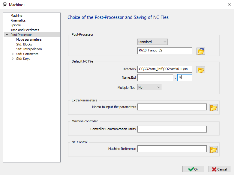
Similarly to MTE, for simulation with robot and program generation, a post-processor needs to be selected. In the machining tree, again open the Machine window and go to the Post Processor menu. Keep the PP type as Standard and then choose the right PP for the robot. In this case, it’s a FANUC robot thus, R610_Fanuc_LS is chosen. If required, the output program name (Name. EXT) and extension name can also be specified. |
|
Robot Strategy Setup
Before simulating the toolpath, we need to setup the Robot strategy, in order to convert the toolpath into Robot motion paths. Click here: Robot Strategy Setup |
|
Simulation
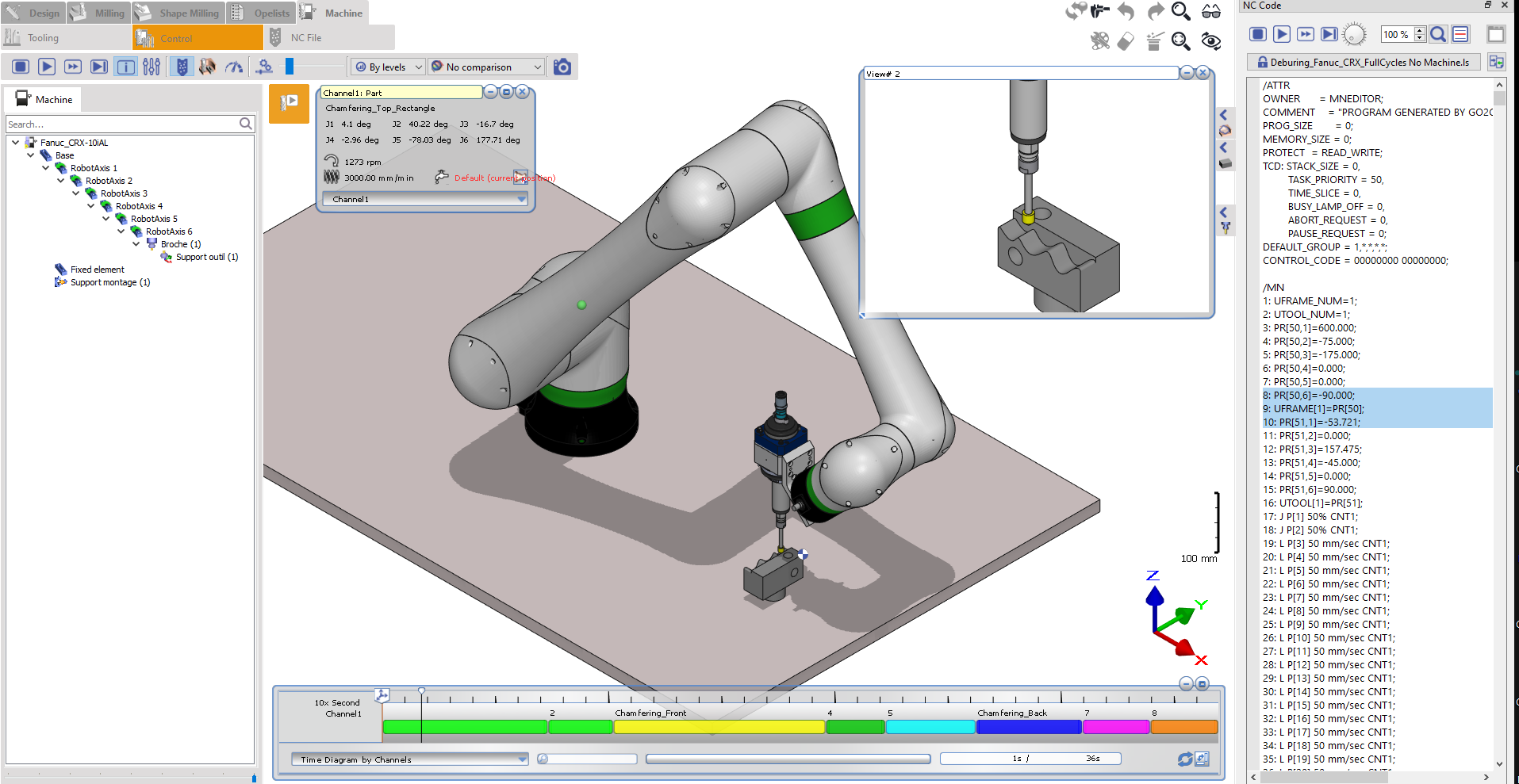
With the machining cycles are defined, the robot selected, the tool and part configured and the Post-processor chosen, the simulation with the robot can be launched in the Control menu. At this point, the parameters and the simulation environment is the same as MTE. |
|
Collision Avoidance
If there is no significant material to remove, it is recommended to set the stock with the same geometry as the part. To do this, duplicate the part and assign it as the stock. Run the simulation with collision check enabled. Check here the several options that are available to avoid collisions: Collision Avoidance. |
|
Robot program output
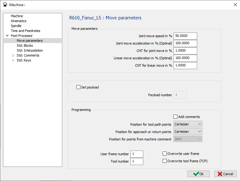
Robot program parameters setting Before generating the robot program, several parameters need to be specified. Joint move speed in %, Joint move acceleration in % (optional), CNT for joint move in %, Linear move acceleration in % (optional), CNT for linear move in % can be configured in the Machine parameters window under the move parameters sub menu in Post Processor. Payload can be set and positioning for toolpath and Approach and Return points can be selected between Cartesian and Joint. |
|
|
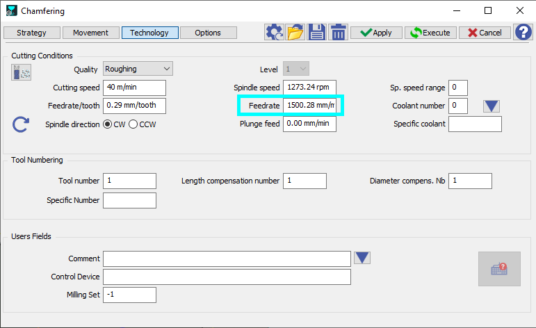
Robot linear speed setting The linear speed for each cycle can be accessed and modified for each cycle strategy under the Technology tab. The Feedrate parameter which is in mm/min governs the linear speed of the robot. Any modification should be applied by clicking Execute to validate the changes. |
|
|
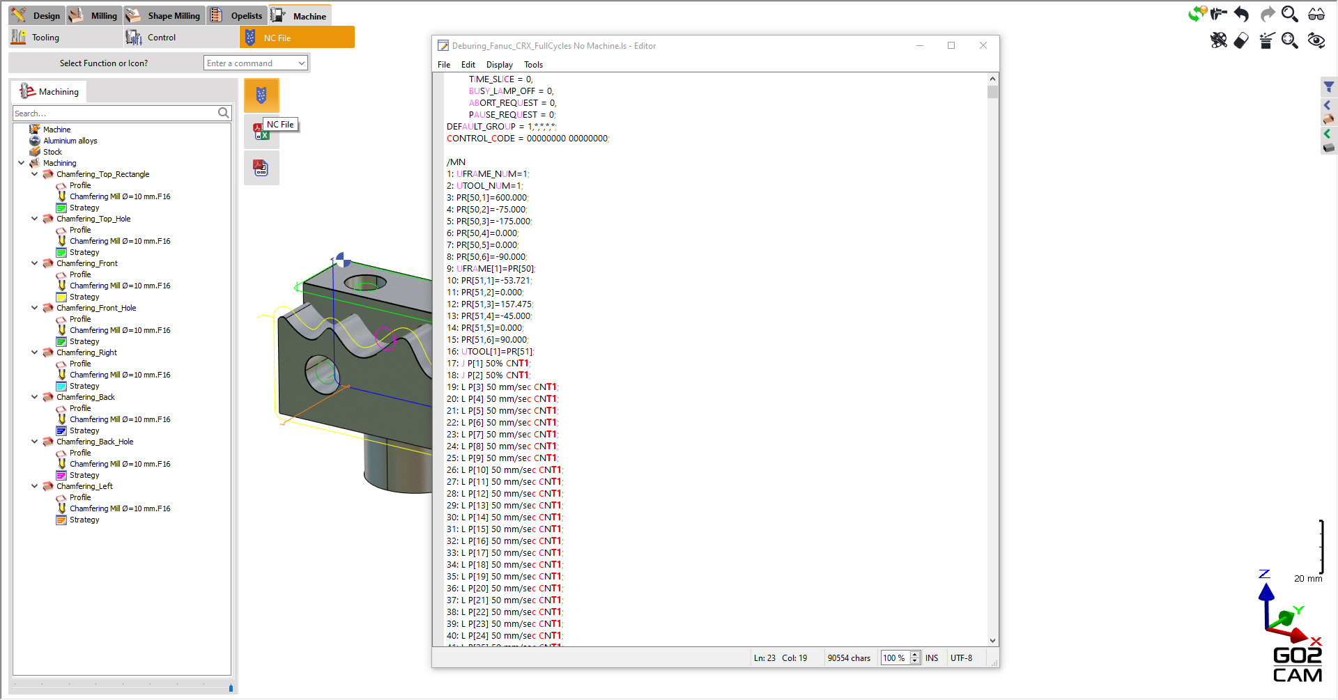
NC output Generate the NC code by clicking on the NC file command in the NC File Sub menu. |
|
|
Watch a video demonstrating the workflow on the right.
|

|
Robot Controller
|
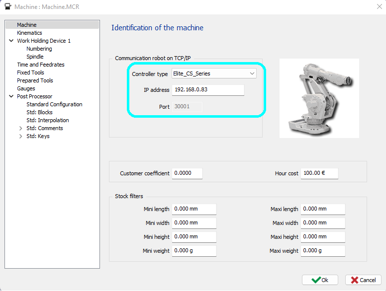
Robot controller connection setting The output program can then be executed on the robot simulator or on the real robot. It’s recommended to run the program in a simulator to validate it. For several robots, it’s possible to connect to the robot controller on IP/TCP or simulator and synchronize the robot movement while the program is running, for this, go to the Machine settings window, select the robot controller type, enter the IP address and port number. On the right is an example. |
|
|
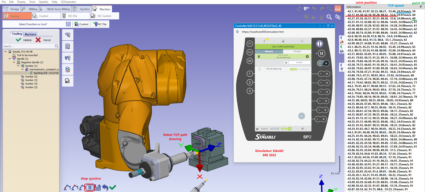
Synchronize in GO2CAM while robot program is running If a real robot or its simulator is running a program, the real position on real time can be synchronized in GO2CAM (not all robots are supported actually). To start synchronization, go to Tooling and select the start synchro icon on the bottom left. Make sure the right tool is selected to draw the right toolpath. Depending on the controller, we can even get the robot TCP linear speed and the point index. |
|