
Presentation

|
GO2cam offers a specialized functionality for geometry tolerancing. Users can define a profile and assign a tolerance to it without modifying the original geometry. Profiles may be generated from any two-dimensional or solid geometry, whether created within GO2cam or imported from external CAD platforms. This functionality is accessible via the Ribbon interface, located in the Manipulations section. |
The tolerancing is available in milling and also in wire-cut EDM.
The tolerancing commands have 2 main purposes:
-
Respect the needed accuracy: definition of a standard tolerance.
-
Modify the part topology: ability to move an element according to another element, by changing the distance or angle value between the 2 elements.
The following example introduces these 2 functionalities:
|
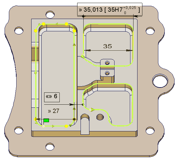
Accuracy: The pocket on the right top hand side corner is 35 mm wide. This is the value found by the control. The draft precises that the general tolerancing is H7. Thanks to the tolerancing, you can apply this value to the dimension and choose to machine the average value. In this case, this is the value 35.0125 mm. Topology: The wall between the pockets is 6mm in reality (read on the draft). In the model, the value is 5 mm. You can fix this mistake in the tolerancing menu. The whole pocket is moved, its width (27) is not modified. |
|
List of Commands
|
|
Profiles Definition |
|
|
Linear Tolerancing |
|
|
Angular Tolerancing |
|
|
Circular Tolerancing |
|
|
Modification |

|
Move of a Tolerancing |
|
|
Profile Cancellation |
Key Points
We want to focus on powerful functionalities of the tolerancing in GO2cam. These options are unique and exclusive on the CAD/CAM market!
We all know how difficult it is for design and manufacturing departments to communicate well together. From machinists point of view, designers do not always take into account the constraints of machining!
One typical case is the definition of tolerances. GO2cam will help you fixing this important issue by providing easy and automatic tools for tolerancing.
Recovering CAD tolerances
|
No need to define again the tolerances, few clicks are enough and the machining will take into account the tolerances defined by the designer! The principle is quite simple: act as if you want to define a new tolerance. First, define the profile, choose the type of tolerance (linear, angular or circular) then click the toleranced elements. At the moment where you should define the tolerance itself, double-click on the CAD tolerance already defined on the draft, the values are recovered directly by GO2cam! |
|
|
▶️ You can watch a video about Recovering CAD tolerances: 
|
Respect dimensions
|
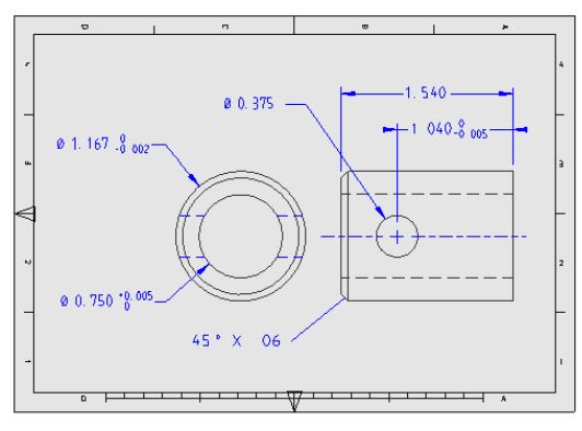
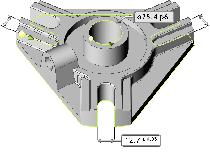
One of the biggest problems for a CAM technician when he imports a CAD model, is that he is obliged to modify many geometries which are tolerance. The reason is that the CAD models are always designed respecting the nominal value of a tolerance! Let’s take a concrete example: the bore hole tolerance of the solid part on the right is 25.4P6. The lower tolerance is -0.031, the upper tolerance is -0.018. Consequently, the geometry drawn with the nominal value 25.4 is simply wrong! It is out of tolerance! With GO2cam, you can modify the dimension easily, and choose to machine it according to the lower, the upper or the average value! |
Machining on average value
|
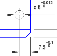
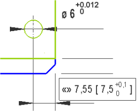
Who never got this question: in my CAD system, can I draw at average value of my tolerance? The answer is NO, but GO2cam enables you to machine the shape taking into account the average tolerance value! In the following example, we make the choice to define the dimension at the average value. This value 7.55 will be the one used for machining. |
|
|
|
▶️ You can watch a video about Tolerancing Circles: 
|
Modification of topology
|
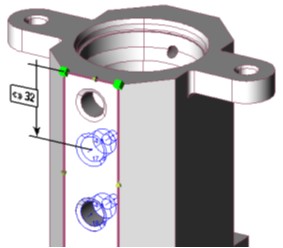
The tolerancing module also enables to modify the topology of a part if necessary. A dimension read on a CAD draft and the real geometry value can be different. Tolerancing will enable you to respect the real dimension without modifying geometry, which can be difficult or maybe impossible. For example, you can move a hole which was defined with the Solid Recognition command. Simply define a ‘tolerance’ between an edge of the face and the hole and change the dimension. The hole is moved and will be machined at its new position, without modifying the geometry by itself. |
|
Keep History
|
The tolerances are applied on profiles, not directly on the geometry. It means that we do not modify the original CAD model received from CAD department or from the customer. The advantage is the ability to modify the tolerance value as many times as needed. You can apply machining and modify the tolerance after this, the history will be kept. |
|