
Presentation

|
Transformation of points, arcs and circles into hole entities with useful information for the machining. |
|
|
All parameters have been regrouped in the dialog box. Geometrical Filters icons are updated with texts and drop-down lists Selection box has been added for entities. Choice between Standard and Users holes is now easily accessible. Users have the ability to choose to delete geometry support/concentric elements or not. |

|
Notes :
-
it is obligatory to transform points into holes to machine them.
-
when defining the machining operations, to recover the length of the hole, go in strategy page and put the parameter Depth/ref to Entity.
The Process for Holes Assignment
1/ Selection of Entities
The first step involves the selection of various entities for the conversion. Multiple filter options are provided to facilitate and speed up the process through a window selection.
The filters governing the recognition of elements during selection are described below:
|
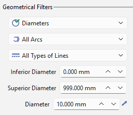
Geometrical Filters: These filters define the geometries that will be recognized and selected. They work as a multi-criteria selection and are segregated as follows:
|
|
|
|
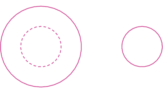
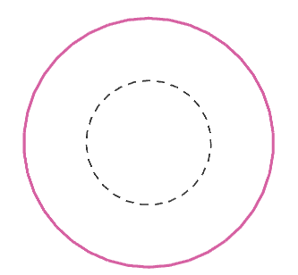
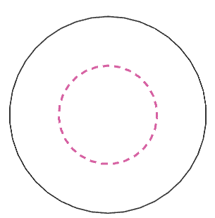
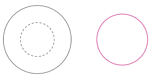
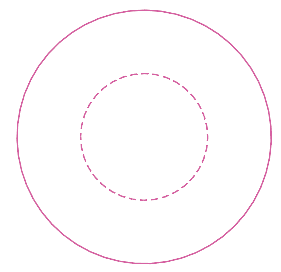
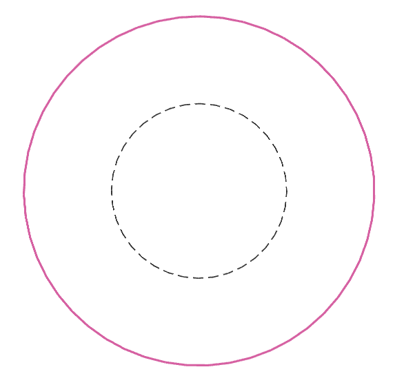
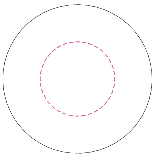
Circular geometries: the selection modes are as per the image below. 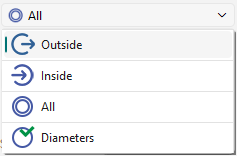
|
|
|
|
|
|
|
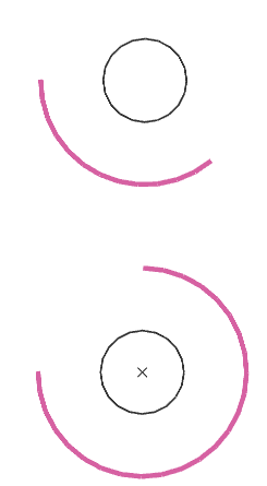
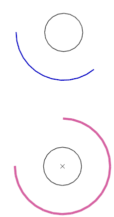
Arcs: choice between selecting all arcs or only those greater than 180 degrees. Fillets are also considered. 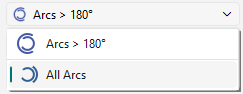
|
|
|
|
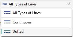
Line types: choice between all line types or only continuous or only dotted.
|
All |
|
Continuous |
Dotted |
|
|
Filters by type of entity: The type of entities to be selected for the transformation are provided as the icons below. These work in tandem with the geometric filters. Blue highlighted icons means they are active. 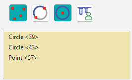
A selection box is also provided to view the list of selected entities, which can be removed/unselected with a right-click. |

Points |

Arcs |

Circles |

Hole models |
|
|
|
|
|
2/ Definition of holes
|
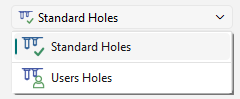
Select between Standard or User hole models.
|
|
|
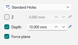
The altitude/Z value, the depth of the hole and creation of a plane can be forced by the checkboxes and definition of values for Z and Depth. Notes : If a single element is selected for transformation, the holes model window is automatically opened based on that defined in the dialog. |
|
3/Transformation of Holes
|
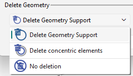
Geometry deletion upon transformation. The user can decide to delete or not, the geometry support or the concentric elements with the drop-down list. |
|
|
On validating, the dialog of the hole model select is opened. Choose the parameters for the hole and finalize to complete the transformation. |
|