
In all the command of planes creation, the selected points can be:
-
points entities,
-
elements extremities (2D or 3D),
-
intersections,
-
random points,
-
points by their coordinates.
3 Points X or Face Plane

|
Creation of a plane by 2 different ways:
|
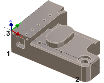
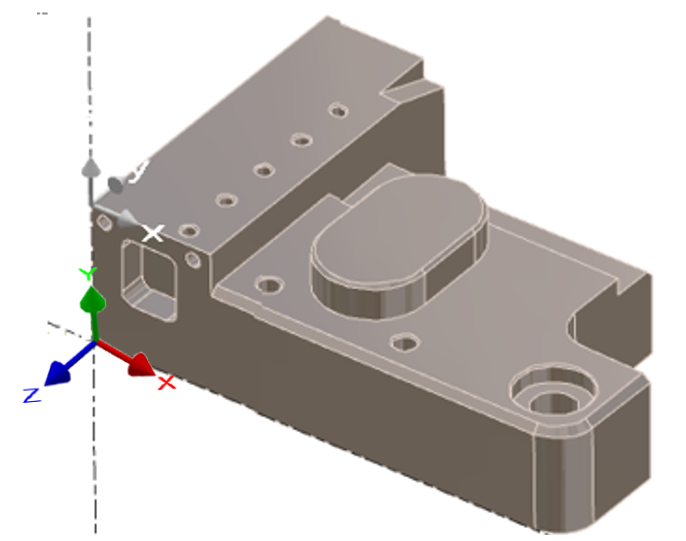
To create a 3 pts X or face plane
|
3 points X |
|
|
|
|
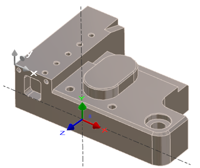
Face plane |
Left click on the face desired (A). |

|
|
2 Points X Plane or Section

|
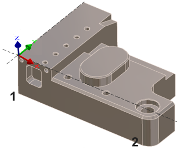
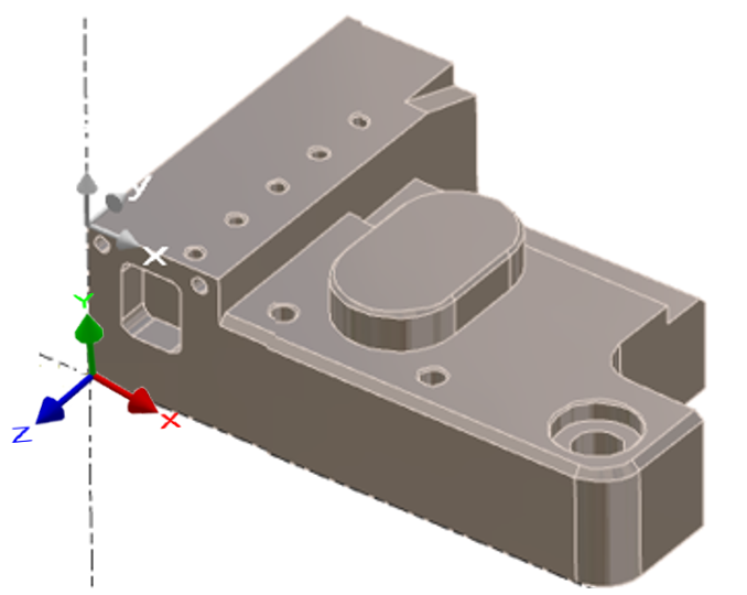
Creation of a plane by two points, this plane is perpendicular to the current plane. |
To create a 2 pts X plane
|
|
|
1 Angle Plane

|
Creation of a plane by rotation around X, Y or Z axis relative to a reference plane. Once the plane is created it becomes the current plane. |
The command is modal, which means that it remains active once the first plane is created. Thus, you can create other planes always depending on the previous one. To stop the command, press the Esc key on the keyboard.
To create a 1 angle plane
|
Choose the rotation axis :
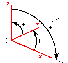
Enter the angle value: to determine the sign, refer to the image on the right.
|
|
|
|
Choose the new plane origin: Left click on a point or enter its coordinates in the dialog zone.
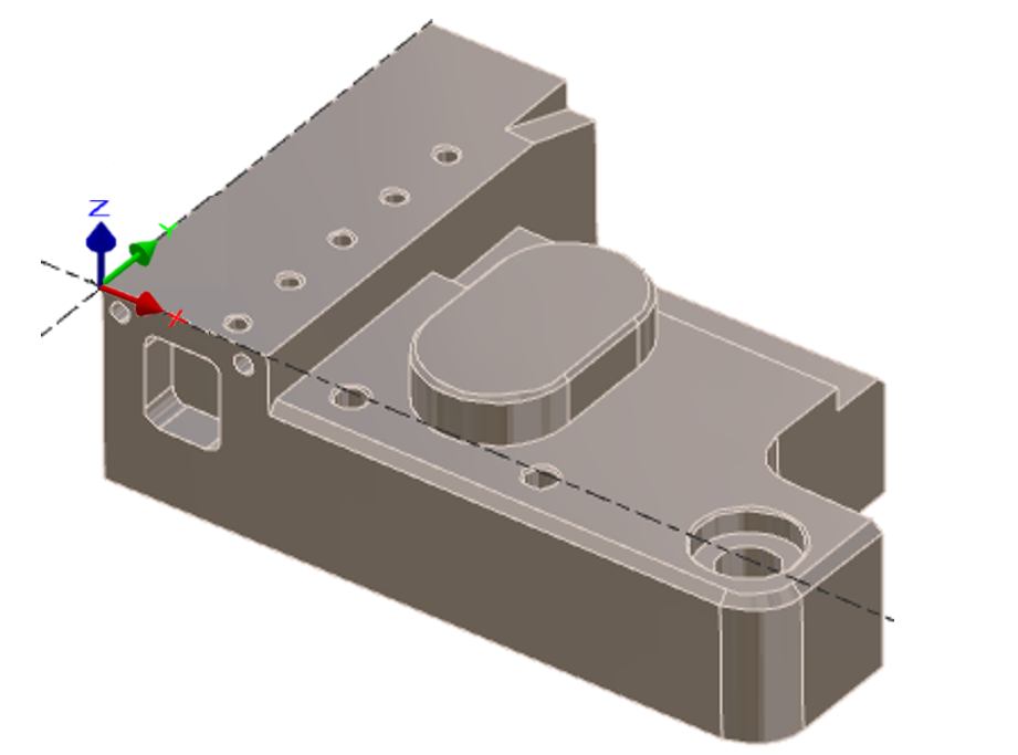
In the following example, this is a rotation (around X) with a + 90° angle (from Y to Z)
|
|
|
Origin Plane

|
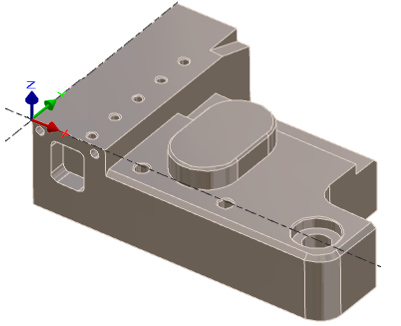
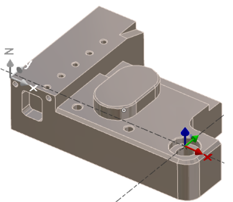
Creation of a plane parallel to the current plane with another origin. The axis orientation is strictly the same than the reference plane. |
To create an origin plane
|
|
|
|
3 points or Face plane

|
Creation of a plane by three points with the possibility to permute the axis and to choose the plane origin. 3 points: you have to show 3 points, the first is a temporary origin, the second and third points give the direction of X and Y axis.
|
3 Points
To create a 3 pts plane:
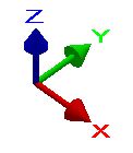
Left click on the solid face desired. |

|
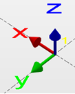
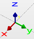
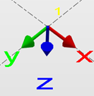
You have now the possibility to permute the axis:
|
Left click on X: X and Y directions are inverted, Z does not move |
Left click on Y: Y takes the place of X, X follows, Z does not move |
Left click on Z: Z and Y direction are inverted, X does not move |
|
|
|
Left click OK to validate.
Left click on the plane origin or define its coordinates in the dialog box.
Face Plane


|

|
Naming of the plane. |

|

|
Plane according to the view |

|

|
Selection of the plane origin on the solid |

|

|
Inversion of the vector direction |

|
|
Orientation of the plane / axis |

|

|
Definition of the X axis from 2 points on the solid |
To create a face plane:
|
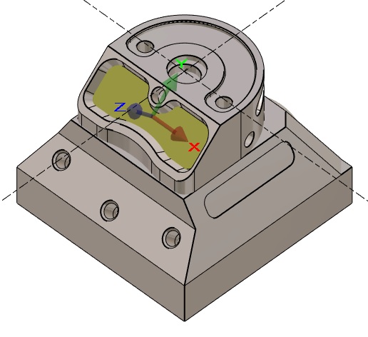
Left click on the 3 pts or face plane icon and then left click on the selected face. |
|
|
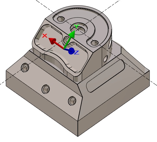
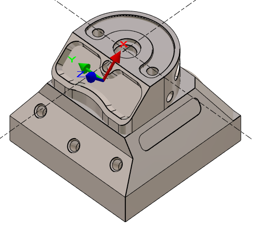
Left click on [4] to invert the axes. Notice: that the X axis has change position compared to the image above. Same for the Z axis. |
|
|
Left click on [6] to define the X-axis. |
|
|
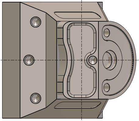
Left click to Validate and the orientation will switch to the new workplane . |
|
|
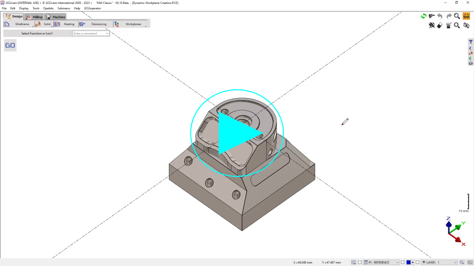
▶️ You can watch a video on Face plane on a solid:
|
Manual Plane

|

|
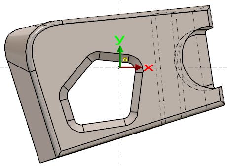
New command to create customized workplane according to the position of the current view. |
|
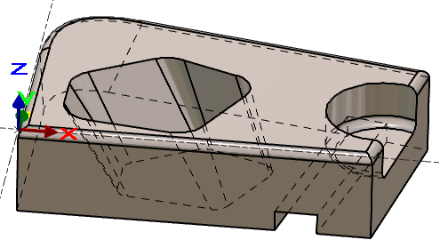
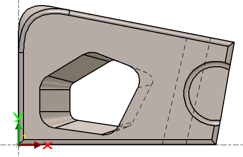
Let’s have a look at this workpiece: we need to machine the through pocket. All the flanks of this shape are tapered and some have an undercut angle in the REFERENCE plane. |
|
|
|
|
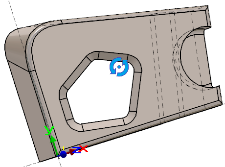
To define a workplane where the tool would access to all the flanks, we have no easy solution. As we do not need a precise angular value, we can use the manual plane:
|
|
|
|