Description of Commands - Part 2
In all the command of planes creation, the selected points can be:
points entities,
elements extremities (2D or 3D),
intersections,
random points,
points by their coordinates.
Plane of Frenet
 | Creation of a plane perpendicular to an entity extremity and with the Z axis tangent to the element. |
To create a Frenet plane
Left click on an element extremity. If the element is a segment:
| 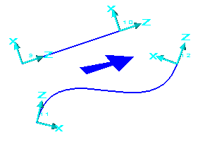 |
3 Angles Plane
 | Creation of a plane by three rotations. There are 4 combinations that enable to reach any position:
|
To determine the sign of the rotation, please look at the convention at 1 Angle Plane.
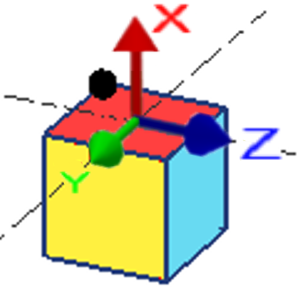
The rotations are successive and depend on the last position: here is a theoretical example with 3 rotations CAC at +90° each time: Warning: the marks XYZ displayed are only done to make easier the understanding.
Start position | 1st Angle: C rotation with + 90° | 2nd Angle: A rotation with + 90° | 3rd angle C rotation with + 90° |
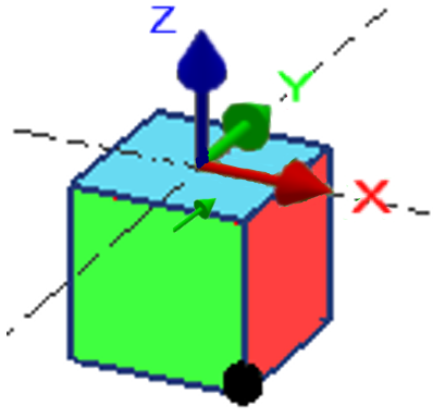 | 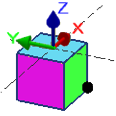 | 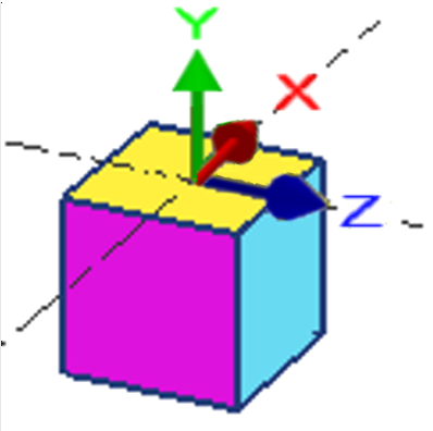 |  |
To create a 3 angles plane
Choose the plane which is going to be the reference plane in the list of plane.
Choose the combination you need in the dialog box
Type in the three rotation angles (in the order of the combination chosen) and validate with the ENTER key each time.
If needed, type in the altitude of the new origin
Left click on the plane origin or define it typing in its coordinates in the dialog box.
Example
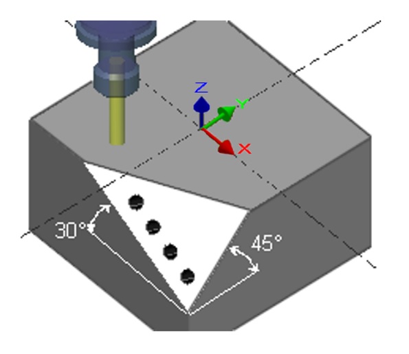
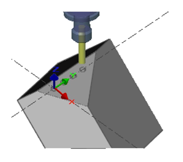
In the case below, we have the rotations C -90°, A -30°, B +45°, the origin point is the center of a hole of the solid, you can select it by pressing the Ctrl and Shift keys and clicking on the edge of the hole at the same time.
 |  |
Profile Cutting Plane
 | Creation of a plane only dedicated to the Profile cutting cycle. This plane is automatically perpendicular to the current plane and defined with an angle relative to the ZX plane. |
To create a profile cutting plane
|  |
Example
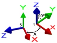
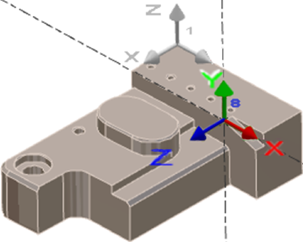
The current plane was the reference plane (1), the angle is 90°, the origin point is different than the origin of the reference plane.
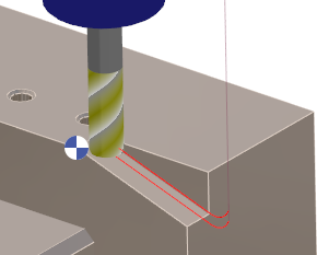
Once the plane (8) is created, the geometry of the slope has to be constructed in the same plane, and finally the profile cutting machining can be defined (still in the same plane).
 |  |
