Creation of Form Tools and Form Inserts
Definition
GO2cam offers the ability to create specific form tools and form inserts, as symbols (*.SYM file format).
The commands for their creation are accessible in the environment ‘Tools Libraries / Form tools’.
 | Form Tool |
 | Form Drill |
 | Form Insert |
 | Form Insert of Threading Tool |
 | Form Insert of Whirling Tool |
Rules of Creation
The method of creation is to define the 2D section of the element, which can be drawn in GO2cam or imported from a CAD software. The method described below is the same for all the the tools and also the toolholders.
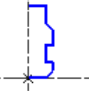
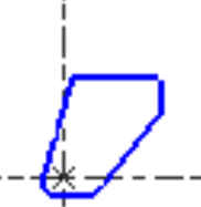
The menu Wireframe gathers the 2D command necessary for the creation of the geometrical profile. The profile must follow precise rules:
|  Specific Toolholder |  Specific Insert |
Complete Process
The process of creation is the same for all types of form tools and form inserts. You can create symbols by designing the shape directly in the specific environment or you can extract the form shape from the final workpiece.
Below, you can watch 2 videos dealing with the creation of a Form Insert dedicated to the machining of grooves on a lathe.


