Design Generalities
General rules
Working Plane
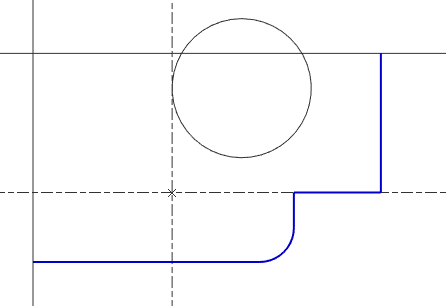
When you enter GO2cam, the 2 lines on the screen are the X and Y axis of the Reference Plane. This is the default plane when you start a draft in milling and EDM. In turning, the coordinate system is different, according to Z and X axis, and the default plane is called Revolution Plane. The coordinates are displayed on the status bar, on the bottom of the screen.
You will start drawing on this plane, if other planes are necessary, you can create them very easily. For more detail about planes: Click here.
Settings
You can choose the units in the Software Configuration (GO2cam logo in the homepage or Tools/Options)
Choosing the numerical system: metric or imperial
Defining the unit: micron, mm, cm etc.
Defining the number of decimals after the coma
AttributesThe colors and the attributes (type of line, thickness etc.) applied to the elements are the ones chosen in the Management of Attributes. The current color has a rapid access in the status bar. The unbounded elements (lines, circles) have a special behavior: they also are given a color, but they are displayed in black color. This option can be changed in Tools / Options / Display, then uncheck the box ‘Only one color for the unbounded elements’. Then you will see the unbounded elements in their ‘real’ color. |  |
When you draw or position any type of element (wireframe or solid), you can call a grid by maintaining the Ctrl key. This grid enables to position elements more easily and accordingly to a predetermined step. The default step value is 5 mm (and 5°) but you can define your own grid step: do a right-click on the background to accede to the popup menu and then choose Grid.
The Contextual cursor
To help you draw with mechanical constraints, GO2cam offers a contextual cursor. This cursor changes according to the type of elements shown and makes the drawing fast and easy.
In the table below is the list of symbols of the cursor. Some notes are added to explain in which situation the cursor will change appearance.
Symbol | Meaning | Explanation |
 | Point or element extremity | Creation of linear element and arc: the element passes through the point. Creation of circle: the point is center of the circle. |
 | Intersection of elements | Creation of linear element and arc: the element passes through the point. Creation of circle: the point is center of the circle. |
 | Middle of segment | To get it: Ctrl + Shift + left click on segment. |
 | Center of arc or circle | To get it: Ctrl + Shift + left click on circle and arc. |
 | Parallelism | Creation of line: parallelism with the selected line or the selected segment. |
 | Perpendicularity | Creation of segment: perpendicularity with the selected line or the selected segment. |
 | Tangency | Creation of line or segment: tangency with circle and arc. Creation of arc: tangency with any element. Creation of circle: tangency with linear element Creation of circle: tangency with arc and circle (but only if the center is already created unless concentricity cursor is displayed). |
 | Concentricity | Creation of circle: concentricity with circle or arc. |
 | Angular Delta | When you create a line passing through a point, you can define this line with an angular delta with another line or segment. |
 | Same radius value | When creating a 2 points arc, at the moment of defining its radius, you can click another arc or circle to recover the radius value. |
 | Impossible action |

