Developed Plane
Creation of Developed Plane
▶️ Please read the explanation below and also note that you can watch tutorial videos at the bottom of page. |
 | Creation of a plane developed around one axis. Choose the distance (diameter of the cylinder) and the axis of rotation. Once the plane is created, you can use any wireframe command to draw geometry inside this plane. It will wrap the geometry around the cylinder. Then you can program 2 axis machining that will be wrapped around the shape. |
You can choose the Z orientation of the tool during the machining. 2 possibilities:
| 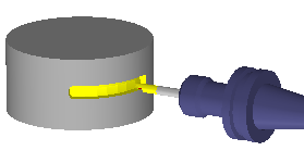 | 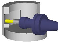 |
Diameter: The diameter on which the unfold is to be created. In the case of a simple unwinding (cylindrical), the diameter can be entered directly here.
Orientation: The orientation of the unwinding plane determines whether the machining will be carried out on the outside or (for large turned parts, possibly with an angle head) on the inside.
Ordinate Unit: you can choose between degrees unit or mm (or inch). This specifies the unit of measurement of the vertical (Y or C) axis in the unfold plane.
Ordinate Direction: with this option you give the direction of the '+', to the Top or to the Bottom
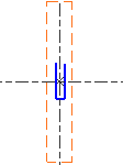 | Bottom Ordinate Direction 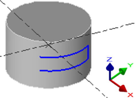 | Top Ordinate Direction 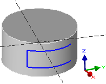 |
Use
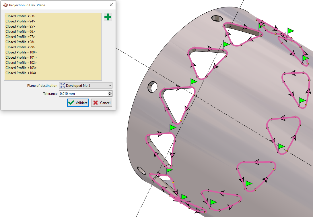
When the plane is created, you can draw in this plane, or import geometry designed in another plane.
You cannot change the view in a developed plane: only top view is available!
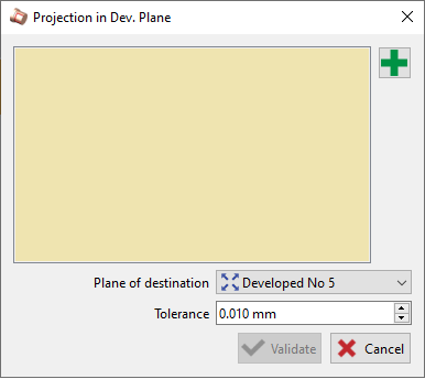
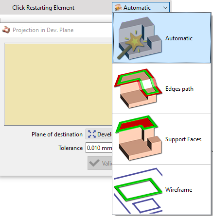
 | The import is done by projection with the command Projection in developed plane available in the menu Workplane. In the command Projection, 4 modes of profile creation are available; Automatic, Edges path, Support faces and Wireframe. |  |
The elements projected into a developed plane are not anymore transformed into polygons. They are kept as arcs and segments, for a better machining result.
Machining in Developed Plane
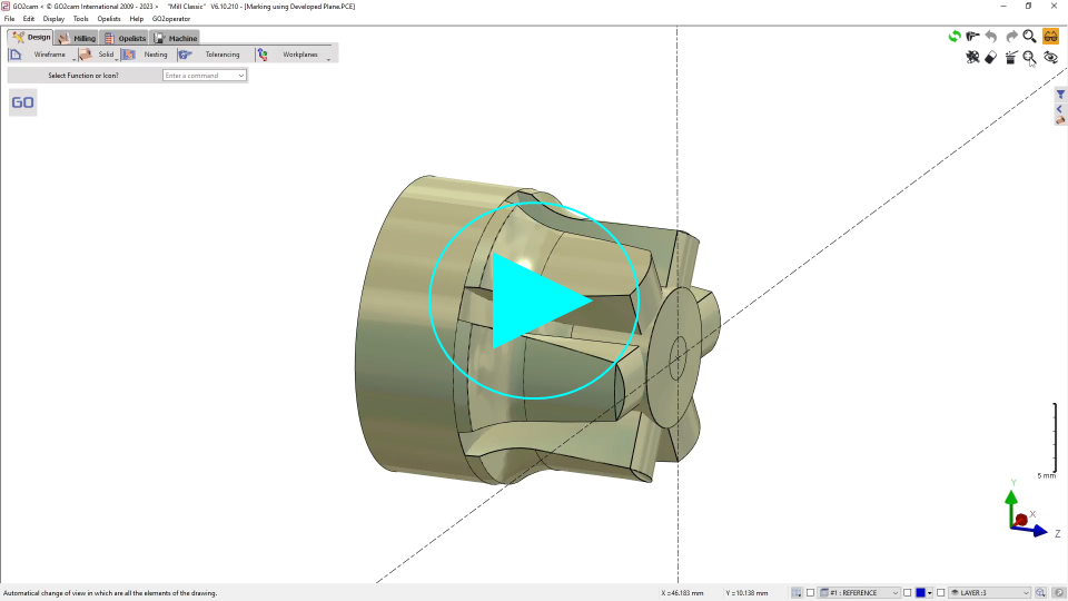
Once the workplane is created, this is very simple: proceed as you do usually with any other shape. Just check that you are currently working in the developed plane. You can program any 2 axis operations, as we show you in the example with a pocket. | 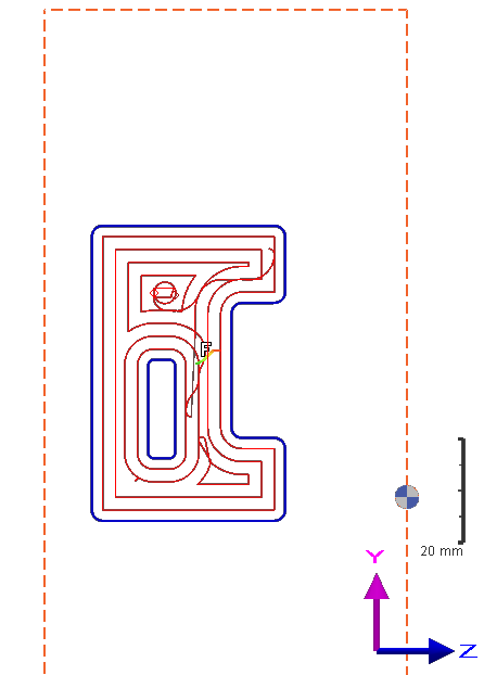 | 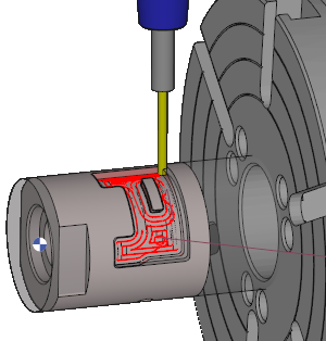 |

