Definition
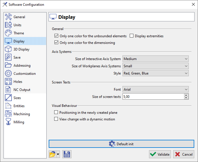
In this page, you will be able to customize your display according to the options listed below.
|
Here we have 4 sections:
|
|
Description and Use
General
-
Only one color for unbounded elements: lines and circles are displayed in a unique color (black by default). If you uncheck this option, theses elements will take the current color as any other bounded wireframe element (such as segment, arc, etc.)
-
Only one color for dimensioning: same as above, for dimensions elements.
-
Display extremities: a symbol is shown the wireframe elements extremities.
Axis Systems
-
Here we can choose the size of the Interactive Axis System (in the bottom right corner).
-
You can also choose the size of the Workplanes Axis Systems, shown on the origins of Workplanes. Usually most of them are hidden, you can check the explanation here: Display Bar.
-
The style enables to choose the colors of the 3 axis X, Y, Z: Standard settings (Red, Green, Blue) or historical colors of GO2cam (Green, Red, Yellow).
Screen Texts
Change the font and size of all the texts displayed on the screen; for instance the result of measure of the Control command, the label of profiles, etc.
Visual Behaviour
-
Positioning in the newly created plane: when a plane is created, it becomes the current plane.
-
View Change with a dynamic motion: the change of views and the zooms are done with a dynamic motion.
|

|
New general behaviour of the software regarding views:
|