Geometry Selection in Wire-cut EDM
Wireframe
Definition of ProfilesGeometry selection is carried out with the selection of the various profiles. This can be done by the command Profile Definition under EDM geom in the Design tab. Threading points for each profile has to be defined after. | |
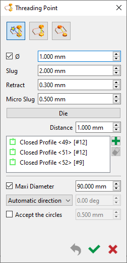
The easiest way to define the profiles is to directly define the Threading point. For Auto threading on profiles, select the wireframe profiles one by one or by window selection, based on the type of cut (Die or Punch). The profile is automatically created with the adequate threading points. |  |
For Taper cuts, define the profiles by the command Taper on profiles under EDM geom in the Design tab. Constant or evolutive taper can be defined. Carry out Auto threading just after. | |
Profile Selection for MachiningSelect the wireframe profiles one by one or by window selection. The threading point is automatically selected. Define the machining altitude (Top Z). Select the type of operation; Die or Punch. Finally choose the type of passes to apply to the selected profiles. | |
Solid
Definition of ProfilesThe definition of the profiles can be done almost fully automatically by the use of the 2 commands under EDM geom; Straight/Taper on Solid and 4 axis on solid. Automatic threading needs to be carried out after. | |
Profile Selection for MachiningSelect the defined profiles one by one or by window selection. The threading point is automatically selected. Define the machining altitude (Top Z). Select the type of operation; Die or Punch. Finally choose the type of passes to apply to the selected profiles. | |
