Deep Drilling Mode
Cycle: Deep Drill & Clevis
▶️ You can watch a video at the bottom of page: Click here |
Definition
This help page explains several parameters all dedicated to the deep drilling mode.
Principle
The deep drilling follows a very precise process:
1. Prepiercing: A prepiercing operation must be programmed in the hole before the deep drilling. The depth of this drilling can be around 1.5 x diameter. For diameter 10mm, a depth of 15mm is necessary. | 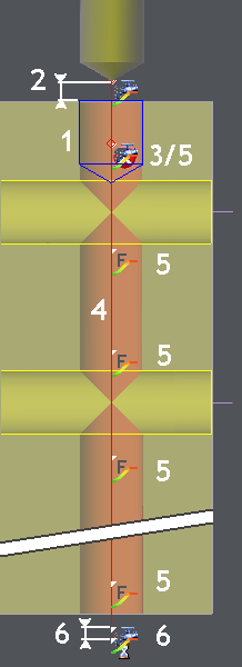 |
2. Tool approach: The spindle speed is reduced, then the spindle is stopped at Safety Distance before going inside the hole. | |
3. Tool engagement: The tool is engaged in the prepierced hole, a stop is set for control operation. | |
4. Machining: The spindle is in normal speed all along the machining. | |
5. Feedrate reduction: The feedrate is reduced at each intersection with another hole. The feedrate can also be reduced at the start of machining, to ensure the good guiding of the drill. If the hole is a through hole, you can also reduce the feedrate before going through. The other holes have to be machined first if you want the intersection to be recognized! | |
6. Retract: A retract and a dwell are defined in the bottom of the hole. After this, the tool is retracted in reduced spindle speed. |
Description of the parameters
Coolant postponed
If set to yes, the coolant is done at the bottom of the prepierced hole.
Spindle speed reduced
Fill the value of spindle speed that you want to program for approach and retract of the drill. The value is expressed in revolution/minute.
Feedrate Reduction Coef
This value is a coefficient relative to the feedrate defined in the Technology.
Starting Distance in reduced feed
If you want to use a reduced spindle speed in the beginning of the hole, define the distance on this field. After this distance, the spindle speed is changed to the normal value (define in the page Technology).
Distance before intersection (A): This distance represents the moment when the feedrate is modified to reduced value before an intersection with another hole. | 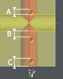 |
Distance after intersection (B): This distance is the moment when the feedrate value is modified to the standard value. | |
Distance before going through (C): For through material holes, you have the ability to reduce the feedrate before going through material. |
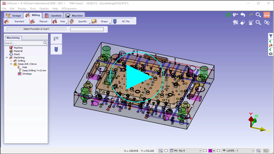
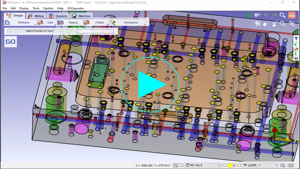
These videos explains how to use Gundrilling in GO2cam.

