Profile Selected and Slot Width
Cycle: Slotting
Any type of slot can be machined, below are few samples with the settings of the strategy:
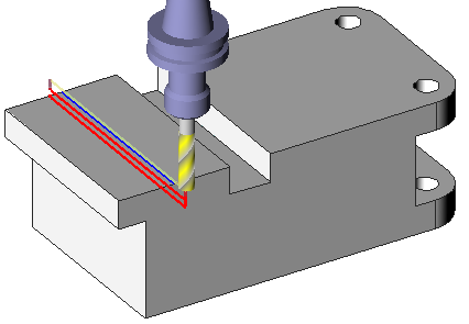
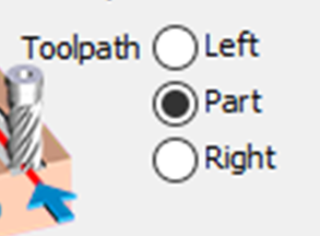
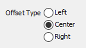
Slotting Center 1 path
The slot is not designed in solid, you have one segment in center of slot:
|  | ||
 |  |  | |
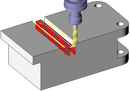
Slotting Side
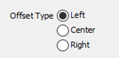
You do not have the center but only the side of the slot. Simply select the segment and define the following settings:
|  | |
 |  | |
Slotting Top and Bottom
In this case both the Toolpath and Offset type have been set to Left. The selection of the profile is done directly on the solid. Choose the altitude also by clicking the solid (-20 and -70). In strategy, select 2 piloted points.  Slot width=0 because we select directly the bottom of slot. | 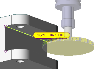 |
With the Z machining set to ‘Middle – depth + alt’, you define the process: - start on middle, - goes down to depth, - then goes on middle, - and goes up to top Altitude. 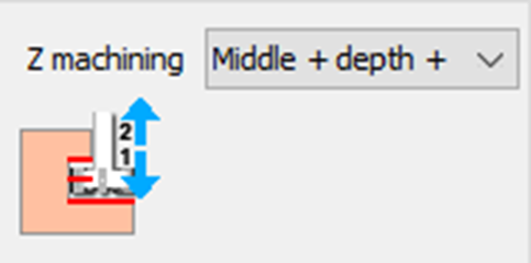 You can check this behavior in the simulation. | 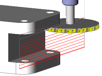 |
Slotting Top
The case is very similar to previous example: the difference is the management of Z machining. Choose Altitude and define the altitude of the top by clicking the solid directly. 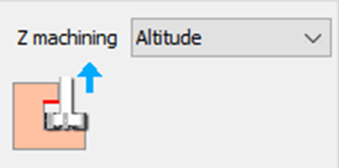 | 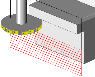 |
Slotting Contour
 | The case is similar to Slotting Centre 1 path. however here, the selection can be done directly by selecting the bottom or the contour profile. This allows to make a slot whose width is the side of tool Choose “Profile selected: Contour” for this strategy. |
