Taper on Profiles - Wire EDM and Milling
Presentation
 | Definition of tapers on the elements of a profile, they can be constant or evolutive, we can add corners on the sharp angles. This function is available both in EDM and in Milling. |
Notes :
the tapers are not geometry, they are information assigned to a profile.
once these information are completed, you need to use the EDM taper cutting cycle or the taper milling cycle to define the toolpath
or you can also create the geometry from a taper with the function 4 Axes Geometry to machine in 4 axes mode (or use shape cycles on the solid created).
▶️ You can watch a video at the bottom of page: click here |
To create a Taper
1. Definition of a profile:
The starting point is white, the first element is dark red. | 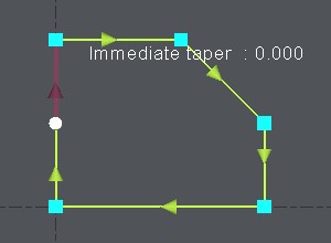 |
2. Dialog Bar:
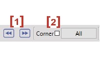
If needed, you can now change the taper value element by element : click on the element to be modified, or use the buttons [3] and [4] to select the previous or the next element. |  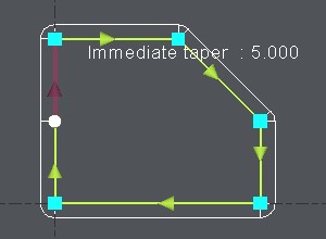 |
|
Note about the taper value: You can also click on a tapered face of a solid to recover directly the value of the taper. First click the 'pipette' icon, then click the face of the solid: the value is automatically read and the taper is built. | 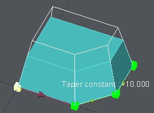 |
3. Evolutive Taper:
On only one element : Click on the element, choose [1] and type in the starting value and the ending value of the evolutive taper. On various elements : Click on the first element, choose [1] and type in the starting value and the ending value of the evolutive taper. Then click on End elt [2] and click on the last element. The example on the right-hand side shows an evolutive taper on 2 elements from 5° to 10°, GO2cam calculates and displays the taper element by element, here the first element runs from 5° to 7.929° and the next one from 7.929° to 10°. |  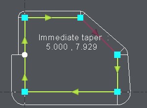 |
4. Conical Corners:
By default, once the first taper is defined, GO2cam generates automatically conical corners on the sharp angles. You can of course change it :
Note about corners : you can also define automatic corners in the strategy page of the taper cutting cycle. In this case they are defined on the whole profile. This is not linked to the corners you can define here in the taper function.
|  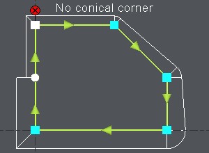 |
5. Confirm:
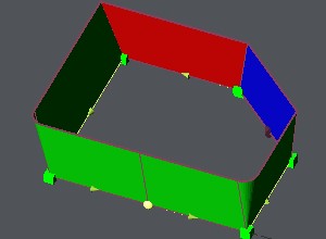
To choose another profile to define a taper on, or to exit the function, click on the Taper on Profile function again . You can also exit the function with the Esc key or choosing another menu or function in GO2cam. The taper is not displayed until you do the selection in the machining editor. The display of the taper is greatly modified. The visualization is in 3D and with a color convention:
In punch mode, green and red are logically inverted. The choice of Die/Punch mode is done in the dialogue zone with a button. You also have the ability to display the colored faces in transparency or not with the icon:
|  |

