The Parametric Geometry
Presentation
GO2cam is fully parametric, which means that you can:
Create family of parts easily,
Modify dimensions,
Do some prototyping, etc.
The way the part is designed is very important to make the part modifiable or not: the parallelism, concentricity, tangency constraints are respected if an element is modified, so that all the elements linked to it are modified too.
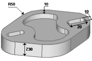 | 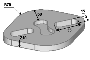 |
Example of a parametric sketch
The aim of this chapter is to learn you the basics of the parametric design.
We will show you here how to design a family of simple parts.
In the following example, 3 dimensions are important.
The distance between the centers of the 2 holes, called L.
The diameters of the 2 holes.
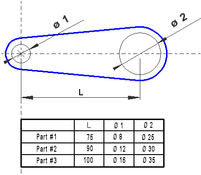
To design a parameterized part, all the geometrical elements must have links with each other’s.
These links are mechanical constraints, such as parallelism, tangency, concentricity etc.
We show you below how to build this part step by step and how to modify it later. You can reproduce it in GO2cam if you want.
Design
Enter GO2cam and Start the drawing by giving a name to the part: Part #1 for example.
Explanation | Images |
Step 1: Click Circle Creation, click on Predefined Circle [1] command. Click the intersection of axes Type 4 (radius) in the dialog, then Enter. |  |
Step 2: Predefined Circle command is still active. Create the center by its coordinates: X=75, Y=0. Type 12.5 for the radius value. | 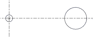 |
Step 3: Predefined Circle command is still active. Click one hole already created, the contextual cursor indicates concentricity (). Type 5 mm as the offset value. Repeat the same actions with the second hole. | 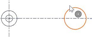 |
Step 4: Click on Segment command. Show consecutively the 2 outside circles you just created, the contextual cursor indicates tangency (). Repeat these actions 2 times to create top and bottom segments. | 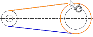 |
Step 5: Click on Drawing command. Pass the cursor on the 2 outside circles and click when the automatic GO2cam suggestion is correct. The part is done. | 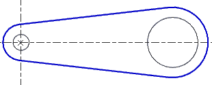 |
Modification
Once the part is finished, save the job as it is with Ctrl+S keys, then go to File, Save As… and choose another name to your part (for example Part #2). You are now ready to modify the part, nothing is simpler!
Go to Edit, then choose Edit Element (shortcut is Ctrl+H). Click the first circle you created, you can modify its characteristics in the dialog zone. Modify the diameter by entering 12. Same action for the second circle, you modify the X position (for the L value) and the diameter. The second part is finished!
You can repeat the same actions for the third part.
If the part was not designed the way we learnt you, the modifications are possible but the whole shape would not move and respect the topology of the part.
