
|
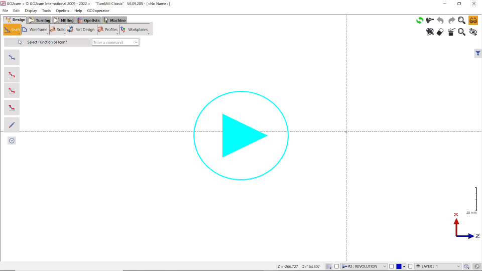
▶️ You can watch a video at the bottom of page: click here |
Presentation
The shaft creation is a specific command to draw turning parts in wireframe geometry. You can find this command in a menu called Shaft in the Turning module only.
The shaft menu is divided in 4 submenus:
|
|
Shaft Creation |
You find the shaft creation and commands to add fillets, chamfers and also specific stock allowances. |
|
|
Creation |
This menu is a ‘light’ menu of Wireframe/Drawing. You find there the useful commands to combine with the automatic creation of shaft. |
|
|
Drawing Finish |
Same as the Wireframe/Drawing Finish menu. |
|
|
Import Cleaning |
Commands useful when importing 2D CAD files (DXF, DWG…) |
Principle
|
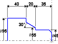
The principle of the Creation of Shaft is an chained design of lengths, diameters and cones, with automatic display of dimensions. The design is also completely parameterized.
|
|
|
|
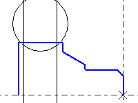
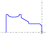
You can combine the shaft creation with wireframe standard commands as shown in the next example for the design of the groove. We use the circle creation then the Drawing command to finish the shape.
|
|
|
|
By default, the design in turning is defined at diameter. To change it to Radius mode, do a right-click on the background and unset the checkbox Revolution Plane Radius. You can watch a short video here showing this function: |
|
The Shaft Creation
|
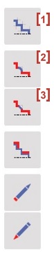
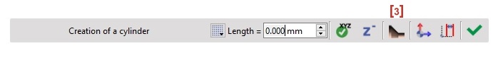
The Shaft Creation [1] is a powerful and easy design tool. The principle is to draw alternatively diameters and lengths and also the shapes of cones. The fillets and chamfers have to be added later, thanks to dedicated the following commands: Fillet [2] , Chamfers [3]
The shaft creation also enables to modify values and update all the calculation (including machining operations). It can be used in case of families of parts. You can create the whole shape without entering any value! In this case, the dimensions will be displayed in pink color, just to remind the user that the dimensions are not fixed yet. |
|
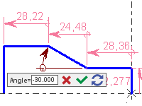
To modify the values, simply double-click on the dimension or on the element, or choose Edit element. The value can be modified in a RapidEdit menu, as shown below. The dimension recovers the black color.
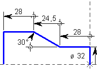
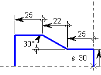
The next example shows the same part drawn on-the-fly, then saved with 2 different sizes.
|
|
|
Use and Features
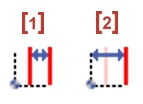
Start the design by selecting a point, then the shaft device activates automatically and alternatively lengths (along Z-axis) [1] and diameters (along X-axis) [2].

To design a cone, click icon [3],
Then choose among the 3 modes of creation:
|
|
Angle and Length |
|
|
Length and Diameter |
|
|
Angle and Diameter |
Then you can be back by clicking on either the Diameter command [4] or the Length command [5].
|
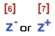
When you enter positive values on the fields, they are applied with direction of the button Z-Minus [6] or Z-Plus [7] |
|
|
In addition to that, you can easily just copy the diameter of a previous one by clicking on its line. This also has the advantage to link the various line segments with each other. As such, if you modify one of the diameter, the others will also change automatically. You can find a video on the right showing this manipulation. |
|
Coordinates system
-
By default, the design is done in relative mode.
-
The user can switch from Relative [1] to Absolute [2] and vice versa by selecting the icon

for Relative and for Absolute mode.
If a dimension is given according to a point that is not the origin of the Revolution plane, you can declare this new ‘origin’ with the button [3] and then click the point. All the next elements will be designed according to this new origin.

Grid: when you design elements, you can maintain the Ctrl key to call the grid with predefined steps values.
|
▶️ You can watch a video showing an example of a Shaft Creation:
|
Advises regarding the display of dimensions
To move the dimensions
Do a right-click on the dimension. Here are 3 commands
|
|
Move |
To move a dimension |
|
|
Text Move |
To move only the text of one dimension |
|
|
Dimensioning Alignment |
To align the dimension to one reference dimension |
To hide the dimensions
|
|
Access to the dialog box of filters |
|
|
In the tab Elements, uncheck the icon to hide all the dimensions (the icon becomes grey). |