
Definition
GO2cam offers the ability to create specific form tools and form inserts, as symbols (*.SYM file format).
The commands for their creation are accessible in the environment ‘Form tools / Tools Libraries’.
|
|
Form Tool |
|
Form Drill
|
|
|
|
|
Form Insert |
|
Form Insert of Threading Tool
|
|
Form Insert of Whirling Tool
|
|
|
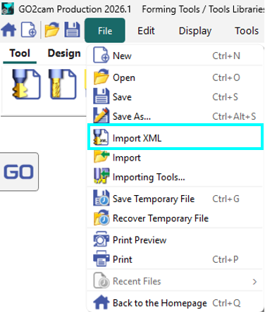
XML Tool Import: You can now open and import XML tool files within the Forming Tools and Tool Libraries, allowing you to modify them directly. |
|
Rules of Creation
The method of creation is to define the 2D section of the element, which can be drawn in GO2cam or imported from a CAD software. The method described below is the same for all the the tools and also the toolholders.
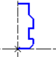
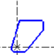
The menu Wireframe gathers the 2D command necessary for the creation of the geometrical profile. The profile must follow precise rules:
|
Specific Toolholder |
Specific Insert |
Complete Process
The creation process is identical for all types of form tools and form inserts. Symbols can be created either by designing the shape directly within the specific environment or by extracting the form shape from the finished workpiece.
Below, two videos demonstrate the creation of a form insert dedicated to the machining of grooves on a lathe.
|
▶️ Watch a video on design of Form Insert. 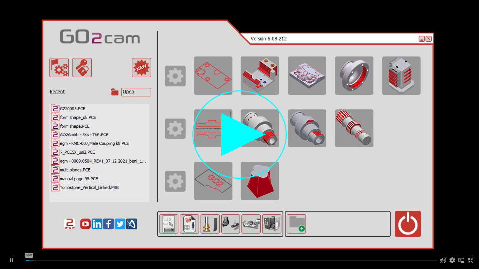
|
|
▶️ Watch a video on the recovery of the shape from the workpiece CAD model. 
|
Process for Swiss Machining Tool
|
In the environment dedicated to symbols creation: a new function, Swiss machining tool is accessible under Creation menu. The whole process for the creation of Swiss machining form tools is now a wizard with the creation steps following one after the other making it more seamless.
Four files have been automatically created:
|
▶️ Watch a video on the new process.
|