
|
|
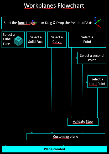
To create planes, navigate to the "Workplanes" menu and choose "Creation of Planes". Creation of Planes provides access to four methods for generating planes:
Note that the Interactive System of axis offers the exact same possibilities for planes creation. |
|
|
▶️ Watch a video at the bottom of page: click here |
||
|
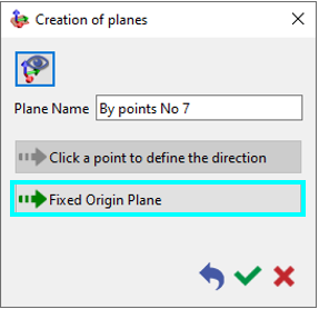
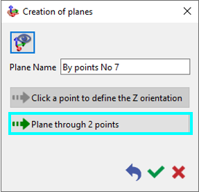
When the Creation of Planes function is accessed, the dialog box shown below appears. This dialog guides the user through the process of creating a plane by selecting points. 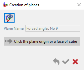
When a plane is created by selecting a solid face, the plane editing dialog opens automatically. |
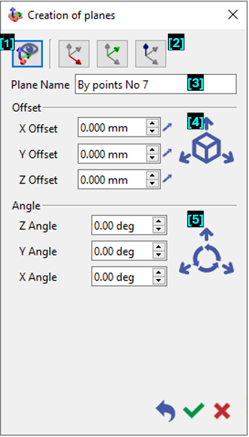
When the Creation of Planes dialog is expanded for further editing, actions such as orienting the axis direction, naming the plane, applying an offset, or specifying an angular adjustment can be performed. 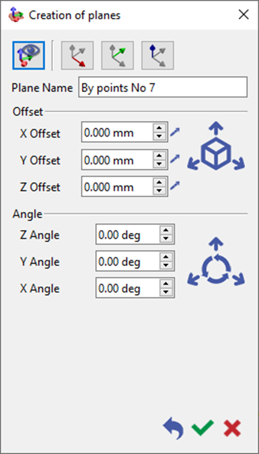
|
|
|
In all the commands of plane creation, the selected points can be:
-
points entities,
-
elements extremities (2D or 3D),
-
intersections,
-
random points,
-
points by their coordinates.
1. Standard Plane
|
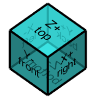
To create a standard plane, align the axis system using the blue cube located at the bottom. Simply select a face of the cube to instantly generate a standard plane corresponding to that face. No editing dialog will appear when creating standard planes, as they are instantly validated upon clicking a face of the blue cube. |
|
|
▶️ Watch on creation of planes. 
|
|
2. Plane from Solid face
|
When creating a plane from a solid face, simply select the desired face in your model, and a plane aligned with that face will be automatically generated.
A plane can also be created by right-clicking on a face and selecting the Plane on Face function. 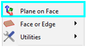
|
|
||||
3. Plane by picking a curve
|
Often referred to as Frenet plane, utilizes a curve entity within the model. Selecting a point on the curve results in the creation of a Frenet plane. The normal vector of this plane is tangent to the curve at the selected point. |
|
|||
4. Plane by picking point(s)
|
1-Point Plane To create a one-point plane, specify a single point in 3D space to define the plane’s origin. Once established, the plane’s orientation can be adjusted through translation or rotation around the origin to achieve precise alignment.
|
|
|||
|
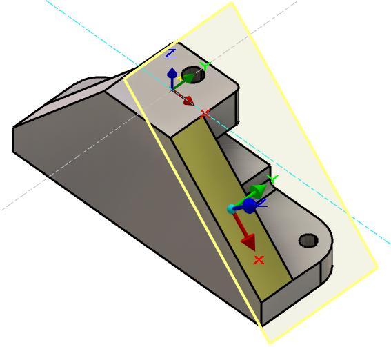
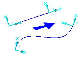
2-Points Plane To create a two-point plane, begin by selecting the first point to serve as the plane’s origin. Then, select a second point to define the direction of the plane’s X-axis relative to the origin. Once confirmed, the plane’s position or orientation can be further refined through optional translation or rotation.
|
|
|||
|
3-Points Plane To create a three-point plane, specify three points: the first defines the origin, the second determines the X-axis direction, and the third establishes the Y-axis direction. This configuration sets the plane’s orientation and normal vector. After validation, the plane’s position or orientation can be further refined through optional translation or rotation. |
||||
|
|
|
This command to create customized workplane according to the position of the current view. |
|
|
Orient the axis direction by selecting a face, segment, or two points. |
||
|
|
Assign a name to the plane being created. |
||
|
|
Offset the plane by either picking a point using the pipette tool or entering specific X, Y, and Z offset values. |
||
|
|
Add an angle to adjust the plane's orientation |
||
|
▶️ Watch a video about Creation of planes below: 
|