
This page is dedicated to Value-Added Resellers (VARs) responsible for installing and configuring NCcontrol at customer sites.
Structure of NCcontrol
The required files and directory structure for NCcontrol are detailed in the downloadable PowerPoint presentation, which includes two explanatory diagrams.
Configuration of the Customer’s PC
When defining a machine at a customer site, follow these steps:
-
Create a Directory for Each Machine
-
For each machine, create a dedicated directory in:
C:\Program Files\GO2cam_Intl\GO2camV612\NCcontrol\Programdata\NC2check\machines
-
-
Machine File Configuration
-
Ensure this directory is referenced in the machine file, specifically in the post-processor page.
-
-
Post-Processor Settings
-
Define the necessary information in the post-processor (PP), especially in the procedure NCcontrolDefineController.
-
For a list of required variables, refer to: Variables for CNC Controllers.
-
Data to download
-
The exportNC.xml file contains information about the MTE machine kinematics, origins list, and tool offsets.
-
This file provides NC2check with the necessary data to analyze and process the NC file accordingly.
-
When generating an NC file, an XML file is exported automatically. It will have the same name as the NC file but with the extension .NCC and will be located in the same directory as the NC output.
|
File Type |
Description |
|
Contains machine kinematics, origins, and tool offsets for NC2check. |
|
|
|
Exported alongside the NC file; same name, .NCC extension, same directory. |
Rules for MCG files
There are two mandatory rules when creating the 3D kinematics machine file:
-
The main machine frame component must be named Body (capital B is mandatory).
-
The orientation/direction of each axis is fundamental and must be defined correctly.
|
Linear Axis 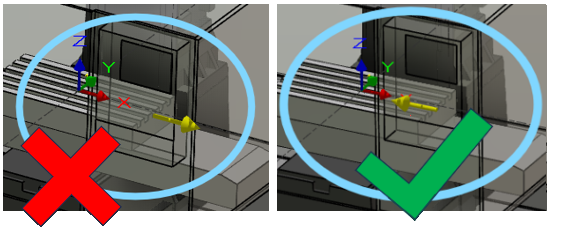
|
Rotary Axis 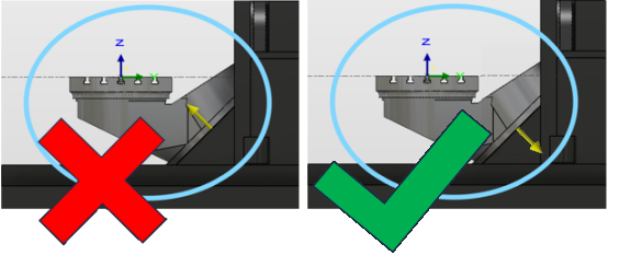
|