
Cycle: Contouring, Contour Rework, Profile Cutting, Slotting, Taper Cutting, Chamfering
|
|
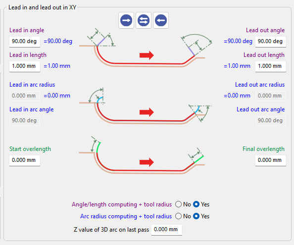
Learn more about the interface for the Lead in/Lead out parameters, by clicking the link here. |
|
Overview
These functions define the Lead in and Lead out arc radii and angles, which control how the tool enters and exits the material using tangential arc movements. The radii determine the curvature of the entry and exit arcs, while the arc angles define their extent. Together, these parameters ensure smooth engagement and disengagement of the tool, improving surface quality and machining continuity.
This option is used in several machining cycles, with different purposes and behaviors.
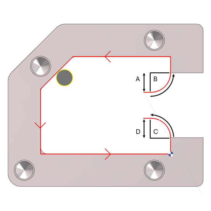
Lead out arc angle = 45° |
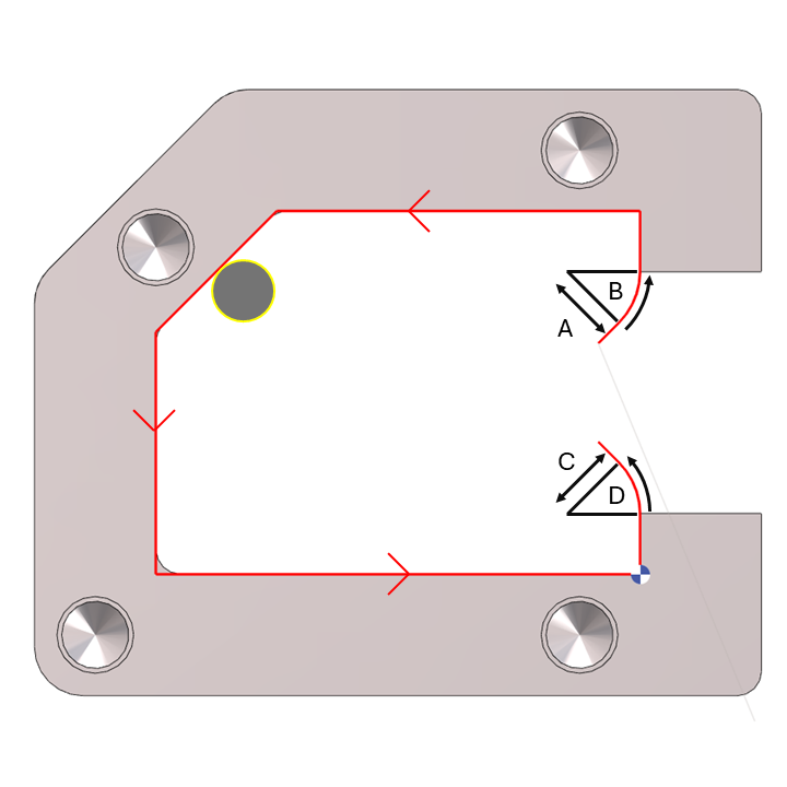
Lead in/Lead out arc angle = 90° |
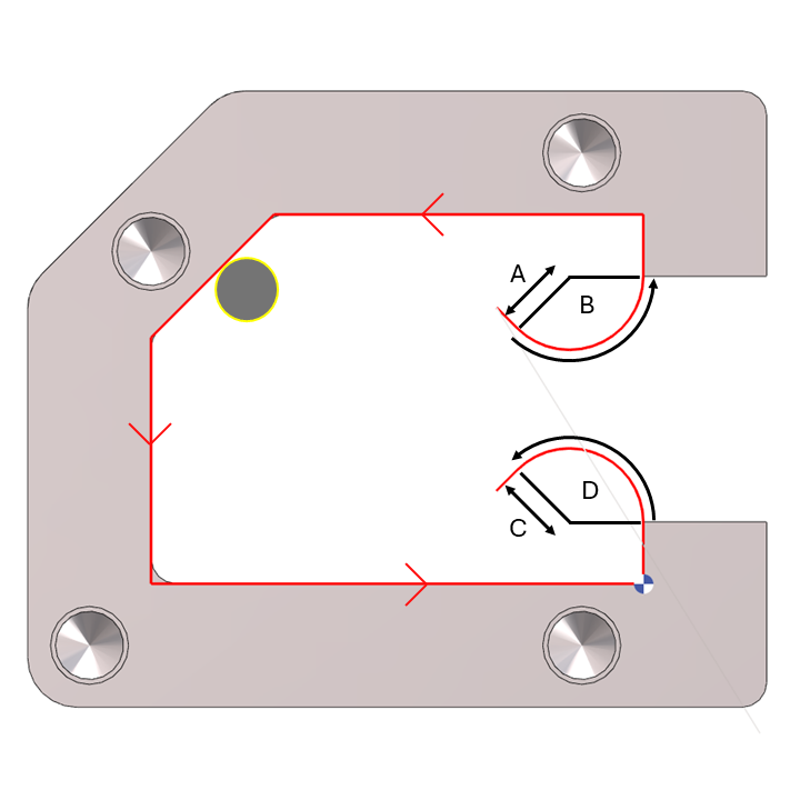
Lead in/Lead out arc angle = 135° |
A. Lead in Arc Radius
The Lead in arc radius creates a tangential arc at the beginning of the toolpath, allowing a smooth entry into the cut and improving surface quality. This is particularly useful when contouring starts in the middle of a line or an arc. The radius must be greater than the tool radius. |
||
B. Lead in Arc Angle
The Lead in arc angle controls the length of the entry arc. Adjusting this value changes the extent of the arc used for the tool entry. |
||
C. Lead out Arc Radius
The Lead out arc radius defines a tangential arc at the end of the toolpath, ensuring a smooth exit from the cut and helping to prevent marks on the finished surface. The radius must be greater than the tool radius. |
||
D. Lead out Arc Angle
The Lead out arc angle controls the length of the exit arc. Adjusting this value changes the extent of the arc used for the tool exit.
|
||
|
▶️ Watch a video on Lead in/Lead out : Arc Radius and Arc Angle. 
|
||
Cycle: Chamfering
|
|
Chamfering cycle has been improved to offer greater flexibility during tool positioning. Lead in and lead out arcs are no longer restricted to a 90° angle. |
▶️ Watch a video about Lead in/Lead out arc angle for chamfering. 
|