
Presentation
These commands enable to optimize the toolpath between selected holes and between selected profiles.
Optimization is available for Holes machining, Pockets and Contours in milling and Straight, Taper and Pocket Cutting in EDM. It is located in the dialogue bar during the selection of the cycles.
First, the available functions will be described, followed by instructions on optimizing the path between holes and between profiles.
1. Optimization commands
|
|
Profiles Manual Organization |
The path can be defined manually by displaying the holes or profiles in your desired order. |
|
|
Optimization Origin |
Choose the hole or the profile where the machining starts. |
|
|
Types of Optimization |
Choose the best path among 20 solutions. |
|
|
Polar Optimization |
Generates a circular toolpath motion with respect to a defined center of rotation. (Only for Holes Optimization) |
Types of Optimization
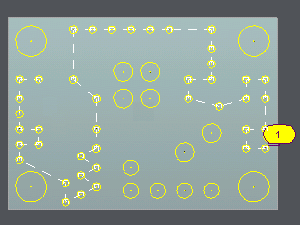
The sixteen first choices are especially useful in case of holes drawn up on a line or on a grid. In these cases, the origin point is chosen automatically.
|
|
The toolpath is horizontal with 2 directions sweep. |
|
|
The toolpath is horizontal with 1 direction sweep. |
|
|
The toolpath is vertical with 2 directions sweep. |
|
|
The toolpath is vertical with 1 direction sweep. |
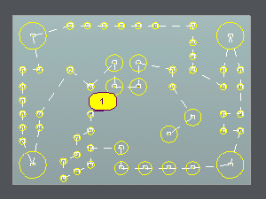
The four most recent options correspond to automatic calculations. Each should be simulated to determine the most suitable choice for the user’s case. Modifying the origin point may yield more efficient toolpaths..
|
|
Near to near path optimization |
|
Taxi distance path optimization |
|
|
Euclidian distance path optimization |
|
Max (X,Y) distance path optimization |
|
|
No optimization: the order taken is the order of creation of the elements. |
||
2. Optimization of paths
Two distinct processes can be distinguished, depending on whether the paths are optimized between holes or between profiles.
Holes Optimization
a. Click on
b. Two cases are possible, and in both, the path length is displayed in the message box. Consequently, several scenarios can be simulated to select the shortest path.
|
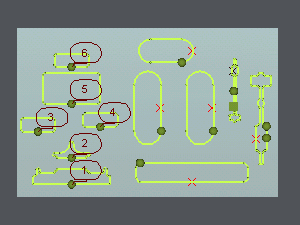
1. Manual Selection: Click then show the holes in the order you want. Options during the selection:
|
2. Automatic Optimization: Do a selection box then choose one type of optimization. If the holes have been created in the correct order, choose No optimization to respect this order. Change the origin of the optimization to multiply the path solutions. Automatic and manual optimization can be combined. First, select an automatic optimization, then use the manual icon to insert, delete, or invert holes. |
|
|
|
▶️ Watch a video on Automatic Optimization.
|
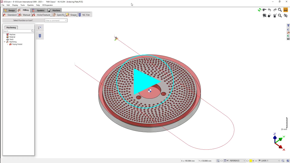
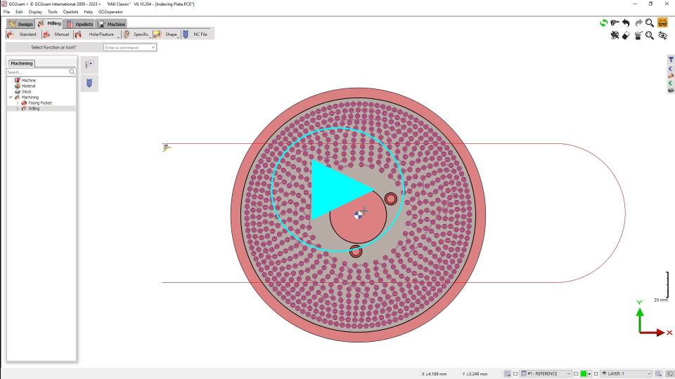
Polar Optimization
This command enables the generation of a circular toolpath on a workpiece containing multiple holes arranged in a circular pattern.
The starting point of the optimization can also be specified..
Steps for Polar Optimization:
-
Select the first hole.
-
Use the multiple selection arrow to select all the holes.
-
Click on the polar optimization icon and define the center of rotation
-
Select the drilling tool.
-
Select the drilling cycle.
-
Calculate.
|
▶️ Watch a video on how use polar optimization on multiple holes.
|
Profiles Optimization
a. Click on the cycles selection icon
b. Two cases are possible:
|
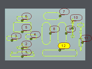
1. Manual Selection The order can be defined manually when the number of profiles to be machined is limited. The profiles to be machined can be selected individually by clicking them in the desired order. |
2. Automatic Optimization This option is particularly useful when machining a large number of profiles. Draw a selection box around the profiles to be machined. Automatic optimization can then be selected, or manual optimization. |
|
|