

|
Open Area on Profile defines which sections of a machining boundary are open. The tool can enter or leave the machining area through these sections. The command applies to wireframe profiles and recognized pocket features on solids, with different selection rules. |
|
Geometry selected |
Use the command to |
|
Wireframe profile |
Declare open sides after selecting a pocket boundary, which is initially considered closed. |
|
Solid pocket feature |
Close originally open sections of a recognized feature, then reopen them when required. |
1. Wireframe Profiles
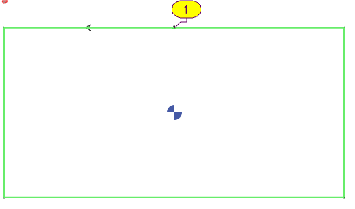
In Standard milling, select the pocket profiles first. A selected pocket boundary is initially closed.
|
Before: closed pocket |
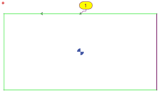
After: one open side |
|---|---|
|
|
Define the Open Sides
-
Select the pocket profile or profiles.
-
Activate Open Area on Profile.
-
Click the boundary elements that are open to the outside.
-
Check the result: purple elements are open; green elements remain closed.
-
Define the required Top Z and Bottom Z, then validate the geometry.
|
Selection |
Result |
|
Click a profile element |
Define the required element as an open section and check its purple display. |
|
Click the profile bubble |
Set the whole profile open. Check that the entire required boundary is purple before validating. |
Whole-Profile Example
The following example shows the outer boundary declared fully open using its selection bubble. Check inner profiles separately: the island must retain its intended role.

Effect on the Toolpath
The following example compares machining with a closed boundary and with an open side. The open-side definition changes the tool entry and exit route. Recalculate and check the toolpath after changing the boundary state.
|
Closed-pocket example |
Open-side example |

|

|

2. Pocket Features on Solids
For a recognized pocket feature, use this command to close an open section locally or change all eligible open sections together. Select the corresponding feature face, rather than following the wireframe element-selection procedure.
Close or Reopen a Feature Section
-
Select the pocket feature whose open areas must be adjusted.
-
Activate Open Area on Profile.
-
Click the face corresponding to the originally open section to close it. The same eligible section can be reopened when required.
-
For a range or the whole feature, use the selection methods below.
-
Check the resulting open/closed sections and the machining toolpath before continuing.
|
Action |
Use |
|
Click the corresponding face |
Close or reopen one eligible section of the feature. |
|
Shift + click two elements |
Open or close the elements between the two selected ones. |
|
Click the feature bubble |
Toggle the state of the entire feature, subject to the eligibility restriction below. |
|
Face appears red when hovered |
The face cannot be modified using this command. |
Important — solid-feature restriction: only sections that were originally open in the recognized feature can be closed and reopened. This command does not make an originally closed solid wall into a new opening.
Watch: close open sections of a recognized solid pocket feature.

Related Topics
-
Pocket and Island Selection on Wireframe — select the pocket and identify material to preserve.
-
Wireframe Profile Selection — define a manual profile and its endpoints.
-
Z Altitudes on Wireframe — define or recover the machining levels.