
Presentation
|
|
|
This page explains how to define and assign origins to the workpiece. It also describes how to specify custom syntax for the origins. |
1. Program Origin
|
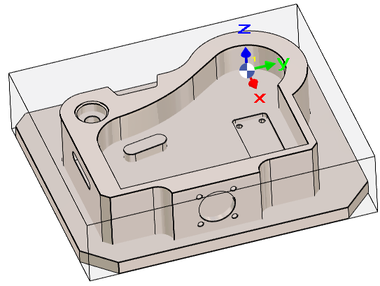
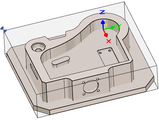
By default, the Program Origin is the origin of the REFERENCE plane. When accessing the Milling menu, the Program Origin is displayed on the screen using a dedicated symbol. However, the origin may need to be modified for all operations. In such cases, the Move commands must not be used for this purpose. In the Machining Tree, in line Stock, click Single Origin and click the new point.
A Machine file must be loaded to be able to access to the change of origin. This is because the settings of the origins is done in the Machine file. |
|
|
In Wire EDM, the Single Origin command can also be used to redefine the program origin.
It will create a new origin but still keep the Z0, only X and Y positions will be modified!
2. Multiple Origins
|
The mechanism for defining origins is unified with the MTE module, providing a consistent workflow across both environments. This is particularly useful when a project requires multiple origins for different machining setups. The process is as follows:
|
|
|
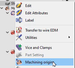
To access the command, in the machining tree, right click on Stock and choose Machining origins. |
|
|
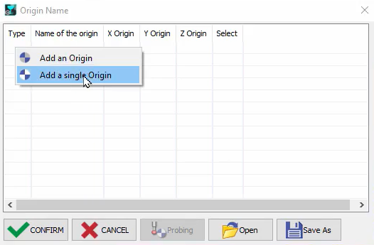
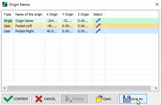
In the pop-up table, right click on a blank cell then choose Add an origin or Add a single Origin.
|
|
|
Use the selection Pipette on the row and choose a point on the solid to define the origin. Using the same principle, multiple origins may be defined on the part, and the origin name may be renamed by double-clicking on it. The configuration can be saved for future use and click on Confirm to validate the origins. |
|
|
Watch a video on the right demonstrating the creation and application of multiple origins. |
|
Multiple origins display
|
|
If multiple origins are defined for the part, they are all visible on the screen. Upon selection of the machining cycle, the corresponding origin marker changes color for better identification. 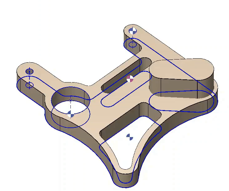
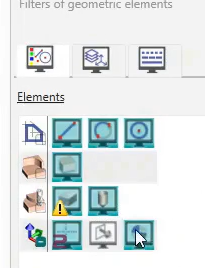
It is also possible to filter out the multiple origin marker within the filters option. |
|
|
Watch a video on the right demonstrating the manipulations related to the machining origins. |

|
3. Assignment of Origins
Once the origins have been created in the origin table, they must be assigned to the operations. Two methods are available, depending on whether the configuration is used with or without MTE.
Process without MTE
|
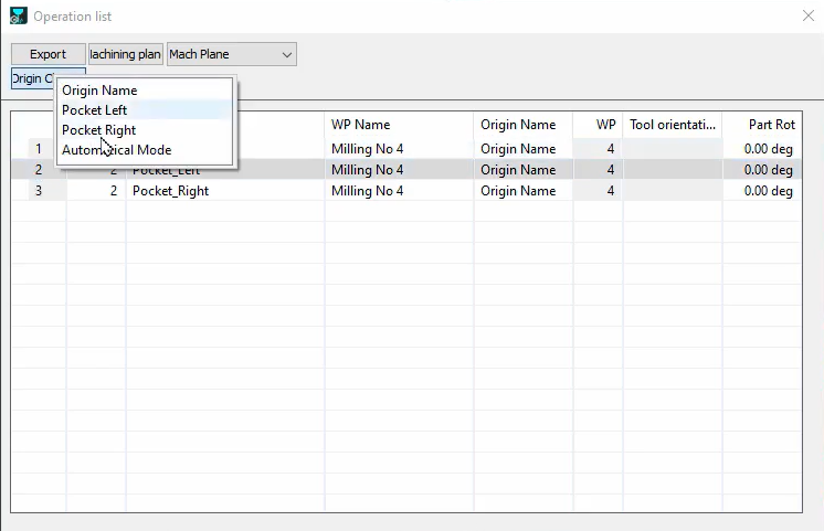
It is necessary to open the Machining List and then select Machining Planes (Mach Plane in the dropdown list). Select the row of the cycle requiring origin change then click on the Origin Change button to access a drop-down list of all the origins defined. Choose the adequate origin for the cycles and simply close the window.
The Origin Change button is not available when the MTE module is active. Please refer to the information provided below. |
|
|
|
|
The easiest method without MTE is available directly during the cycle definition. The origins defined in a file can be accessed during the cycle selection process in the dialog bar. Hence, the origin for each cycle can be directly defined at this point. 
|
Watch the video below showing how to quickly assign origins during cycle definition. 
|
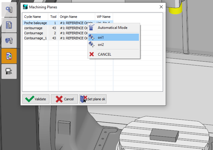
Process with MTE
|
The assignment is done in the Tooling menu, in the command Machining Planes'. Do a right-click in the line of operation and select the needed origin. |
|
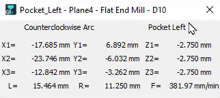
In the simulation, the specific origin for each cycle will be displayed on the screen, and also the labels of the origin will be visible in the coordinates dialog with coordinates taking into consideration the position of the current origin.
The NC file will be calculated according to the defined origins.
4. Origin with Specific Syntax (G55, G56, etc.)
|
It is possible to create origins with a specific syntax that is understood and applied by the standard post-processors. To do that, in the Machining origins command, type the name of the origin with the $ sign in front of the G-code and an underscore _ after. An example is $G55.2_ 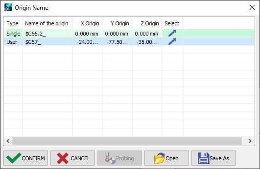
Also ensure that the Origin Name has been defined properly for each cycle in the List of operation: 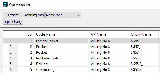
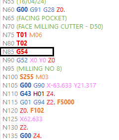
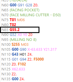
As such, the post-processor recognizes these new origin names and implements them in the G-code file generated. The images below shows the differences in the origin names in the G-code file. |
|
|
|
|
▶️ Watch the video for an example of the process. 
|
|