

|
The command works on solids and 2D profiles: it enables, if a single solid part is present, to automatically recover all the shapes going through to the opposite face just by launching the command.
|
Recognition of Profiles
|
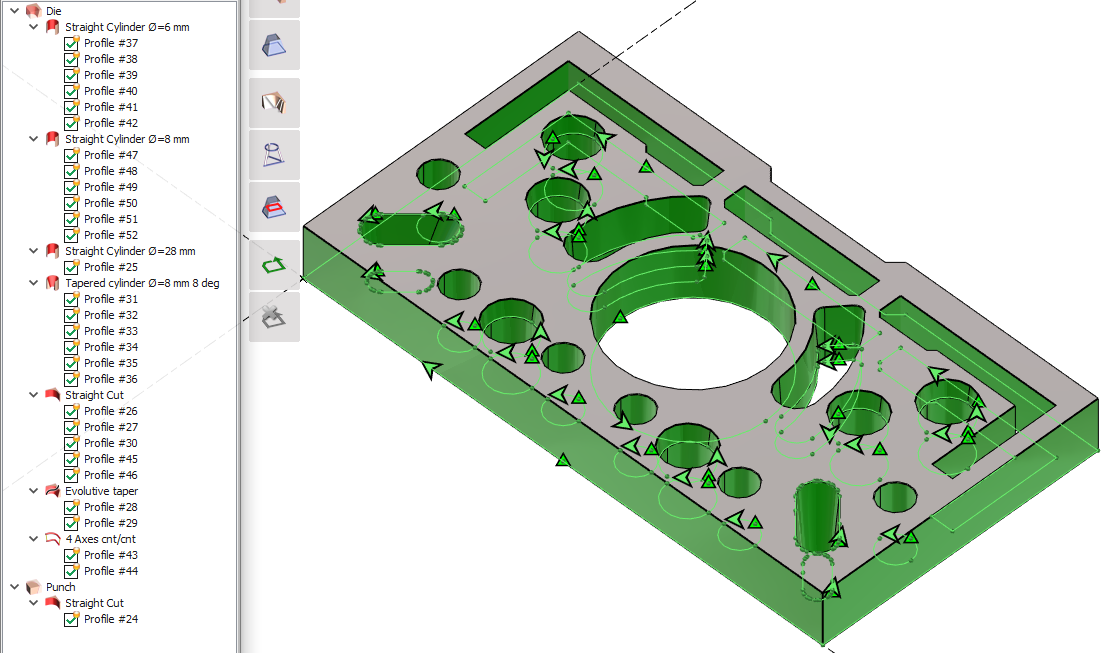
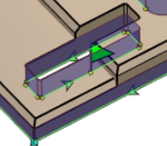
Dies and Punches are recognized, and also all other shapes such as cylinders, constant and evolutive tapers, 4 axis shapes. A tree is created to visualize and analyze the shapes and it also offers some commands, such as the automatic threading on the profiles. You can deactivate/activate the profiles from the tree to hide or show them on the screen. |
|
|
|
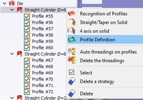
The profile definition is accessible from the tree of profiles, in order to create a profile after having defined a Z section. |
|
|
|
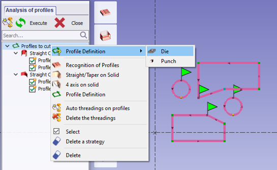
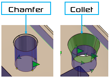
When a profile is created by a Z section, the profile definition enables to choose whether it is a die or a punch shape. |
|
|
|
|
|
|
|
|
|
|
|
▶️ You can watch a video demonstrating the manual usage of this command: 
|
▶️ You can watch a video on maxi taper angle and Faces with different Z levels: 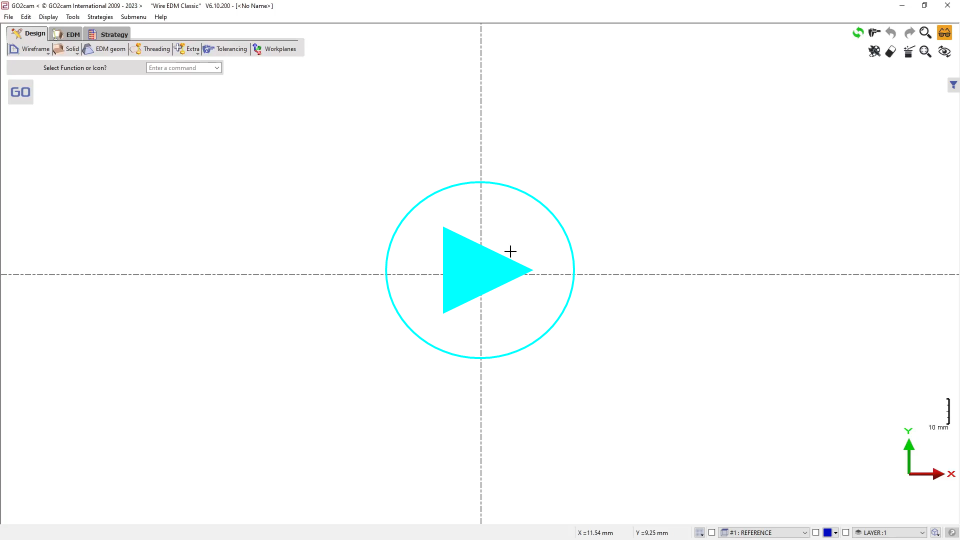
|
Typology
|
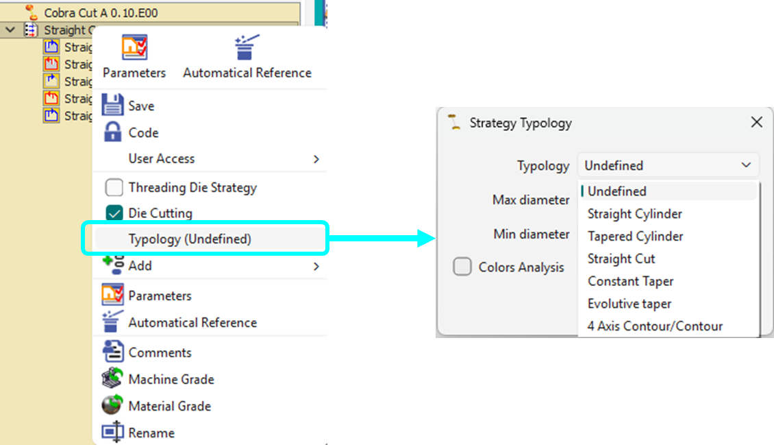
The concept of Typology has been included into the definition of Strategies. During the creation or modification of a strategy, right-click on it to access the Typology command. Several types are available:
|
|
|
|
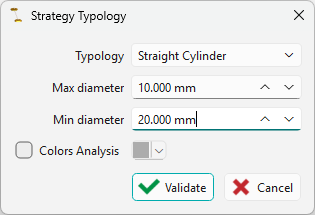
For straight and taper cut profiles, two types are available, one for any shape (Straight Cut, Taper Cut and the other for cylinders ( Straight Cylinder, Tapered Cylinder). This allows to differentiate between the shapes and define separate strategies. A Max diameter and Min diameter can also be defined for cylinder types. This helps to better categorize and group the cylinder typology cycles in the machining tree. |
|
|
|
The strategy Typology window allows to define the automation rule for the selection of strategy during part analysis. This greatly simplifies the process as such:
|

|
|
|
|
Color Analysis Solid faces with assigned colors now automatically generate profiles based on color recognition, with corresponding grouping applied. This is possible because strategy typology can be defined based on color. Simply check the Colors Analysis box and choose the color from the palette to apply to it. In the workflow, the user can toggle Color analysis in the ribbon to apply color strategies. |
|
|
Export Threading Points enables to generate the list of threading points with their coordinates and diameter value. The file format is *.xml. Note: the part analysis also works on 2D Profiles!
|
|