
To start with, the geometry by itself has to be designed either on wireframe or in solid geometry. The specific geometry commands developed for Wire-Cut EDM are applied on standard geometry.
4 menus dedicated to specific Wire-Cut EDM commands are available :
|
|
Wire EDM Drawing |
Submenu of Design / Wireframe, for creation of loops and gears. |
|
|
EDM Geometry |
Specific geometry commands, for the work on solids, the creation of tapers and 4 axes geometry. |
|
|
Threading |
Creation of different types of threading points. |
|
|
Extra |
Access to the options of Nesting and STTM (Swiss Turning Tool Manufacturer) |
Wire EDM Drawing
List of the commands in the Toolbar:
|
|
Alpha Loop |
Creation of loops in the angles, to keep the sharp edges on the punch shape during machining. |
|
|
Omega Loop |
Creation of loops in the angles, to break the angles during the machining of dies. |
|
|
Creation of parallel involute circle gears according to the ISO (NF E 23-001 to 005) and AGMA (American) Standards.
|
|
|
|
|
Creation of rectilinear sides involute circle splines according to the ISO (NF E 22-141) and AGMA (American) Standards. Two types of toothings are possible: Shafts and Hubs. |
|
|
The 'Specific EDM' menu has been renamed 'Mechanical Design' and integrated into other modules. This menu, accessible via Wireframe > Mechanical Design, now includes the aforementioned commands. |
|
|
EDM Geometry
List of the commands in the Toolbar:
|
|
|
The command is only working on solids: it enables, from a click on a flat face, to recover all the shapes going through to the opposite face. Dies and Punches are recognized, and all the shapes: cylinders, constant and evolutive tapers, 4 axis shapes. A tree is created to visualize and analyze the shapes and it also offers some commands, such as the automatic threading.
|
|
|
|
This brand new command enables to create profiles for straight cut and taper by simple click on the solid faces. Click on starting and ending faces and then the starting point. A profile is created, which will be recognized later when creating the threading point. |
|
|
Create the geometry with this command:
Of course, you can combine all these possibilities on one shape. |
|
|
|
This command enables to create profiles for machining by clicking the faces of the solid. Click on starting and ending faces and then the starting point. A new entity ‘double-profile’ is created, which will be recognized later when creating the threading point. |
|
|
|
Still for 4 axes machining, working on solid or wireframe geometry, if top and bottom profiles do not have same number of elements, you can easily define some Synchro Points. |
|
|
|
For some machines, programming tapers is only possible in 4 axes machining. In this case, you start by creating the taper with the command above. After this, use the command 4 Axes geometry to generate automatically the top and bottom profiles necessary for machining, at any needed Z altitude. |
|
|
|
Profile Definition |
Use the Profile Definition command to check that geometric profiles are correct. |
|
|
Profile Cancellation |
Once you created taper, synchro points etc., these information are linked to a profile. By cancelling the profile, you cancel the taper and synchro points. |
Working on a solid is very easy thanks to the commands Straight / Taper on solid and 4 axis on solid. The command Automatic import of wire edm solid is also a great improvement in this field. Click here for more info.
|
▶️ You can watch a video on Solid Import and Machining: 
|
Threading
The creation of threading point is absolutely necessary.
List of the commands in the Toolbar:
|
|
|
||
|
|
|
Auto Threadings on profiles |
You can let GO2cam define the threading automatically (useful in case of many shapes). With the automatic threading, if points have been created in the CAD model, GO2cam recognizes them as the threading location. |
|
|
|
Threading point |
You can choose manually the position of the threading. |
|
|
|
Inclined threading |
Possibility to create the threading through 2 points, giving a tilt angle to the threading |
|
|
Setting multiple slug points enables to divide a geometry in several areas, to machine each area independently by ensuring multiples fastener points. This method is especially used to machine big sized parts or deep parts. |
||
|
|
Profile Cancellation |
Once you created a threading point, a profile is created. Later, if you delete the threading point, the profile still exists, you can cancel it with this command. |
|
|
|
The threading Points are transformed into holes (with jig boring + drilling or drilling only), they can be machined easily in Milling. |
||
Extras
Nesting
The nesting is an optional module which enables to optimize the positioning of multiple shapes in a stock. It is available in Wire-Cut EDM in the menu Design/Extra/Nesting.
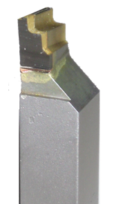
Swiss Turning Tool Manufacturer (STTM)
|
The STTM module enables to manufacture shape tools for turning, especially Swiss turning. This module is an option of Wire-cut EDM. The STTM is a special menu in Design, called ‘Swiss Machining’. Only 10 minutes are necessary to program the toolpaths for such a type of shape, a great time saving for the user! Click here for more information!
|
|