
Presentation
GO2cam integrates Parasolid, a solid engine developed and supported by Siemens Product Lifecycle Management Software Inc.
Parasolid is the leading 3D geometric modeling kernel. GO2cam allows model visualization anytime using OpenGL realistic rendering.
Please read the explanation below and also note that you can watch tutorial videos and practice at the bottom of page.
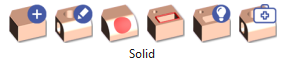
The Solid section is divided in 6 menus:

|
Construction of solid entities based on wireframe geometry (Extrusion, Revolution, etc.) and standard shapes (Sphere, Cylinder, etc.) |
|

|
Combination of solids (Union, Subtraction etc.), finishing (by adding fillets and chamfers) and transformation (Taper, Offset, etc.) |
|

|
Specific commands of operations on the faces (Creation, Extension, Separation, Face Deletion, Deletion of Holes, Stop Faces.) |
|

|
Wireframe |
These commands are dedicated to Edges Extraction, the analysis, the recognition of a model and the creation of 2D entities based on it. |

|
Features |
Solid analysis, Holes recognition and also creation of standard and users holes. |

|
Import Repairing |
Commands to repair and analyze solids from CAD import (STEP, X_T,…). |
Principle
|
You can create a solid by:
|
|
|
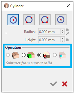
When creating solids, the Boolean operation activates after a second solid is created. It lets you combine solids using union, subtract, or intersect and create an independent solid. We assign color coding to each process (Union: green, Subtraction: red, Intersection: blue). |
|
|
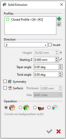
Use the Solid extrusion or solid revolution commands to create 3D shapes from 2D. The Solid Extrusion command is available when wireframe geometry is on screen. You can extrude profiles to create a solid and specify if it will be symmetrical or surfacic. Boolean operations are also available here for faster solid manipulation. Some commands are greyed out or hidden if unavailable.
|
|
|
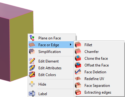
You can edit solid by doing a right-click on the face or edge and have several command at your disposal: Plane on Face: allows you to create a workplane from the selected face. Face or Edge: there is list of commands to modify the selected edge or face. |
|
|
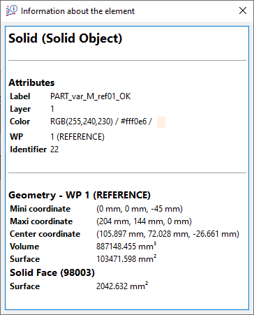
Access to the entity information of the solid by doing a right-click on a face to have information about the whole solid surface or the solid face only as shown on the right. The surface information is also available with the Control command as shown below. 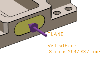
|
|
Your Turn!
Below are the layout diagrams of 2 workpieces that we are going to design. You can either watch the videos to see how to design the workpieces or you can try to design it on your own.
|
Baseplate 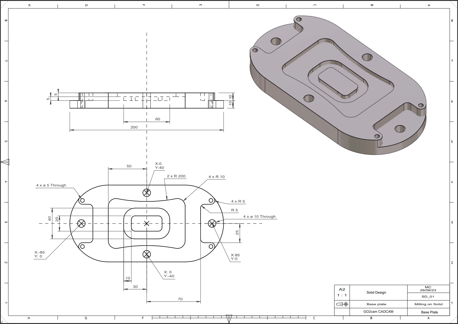
|
This video introduces the creation of a solid using wireframe only using the following commands: Circle, line, drawing, center oblong, rectangle, fillet, duplicate geometry, solid extrusion, move geometry, Boolean Operation 
|
|
Multi Dimension Attachment 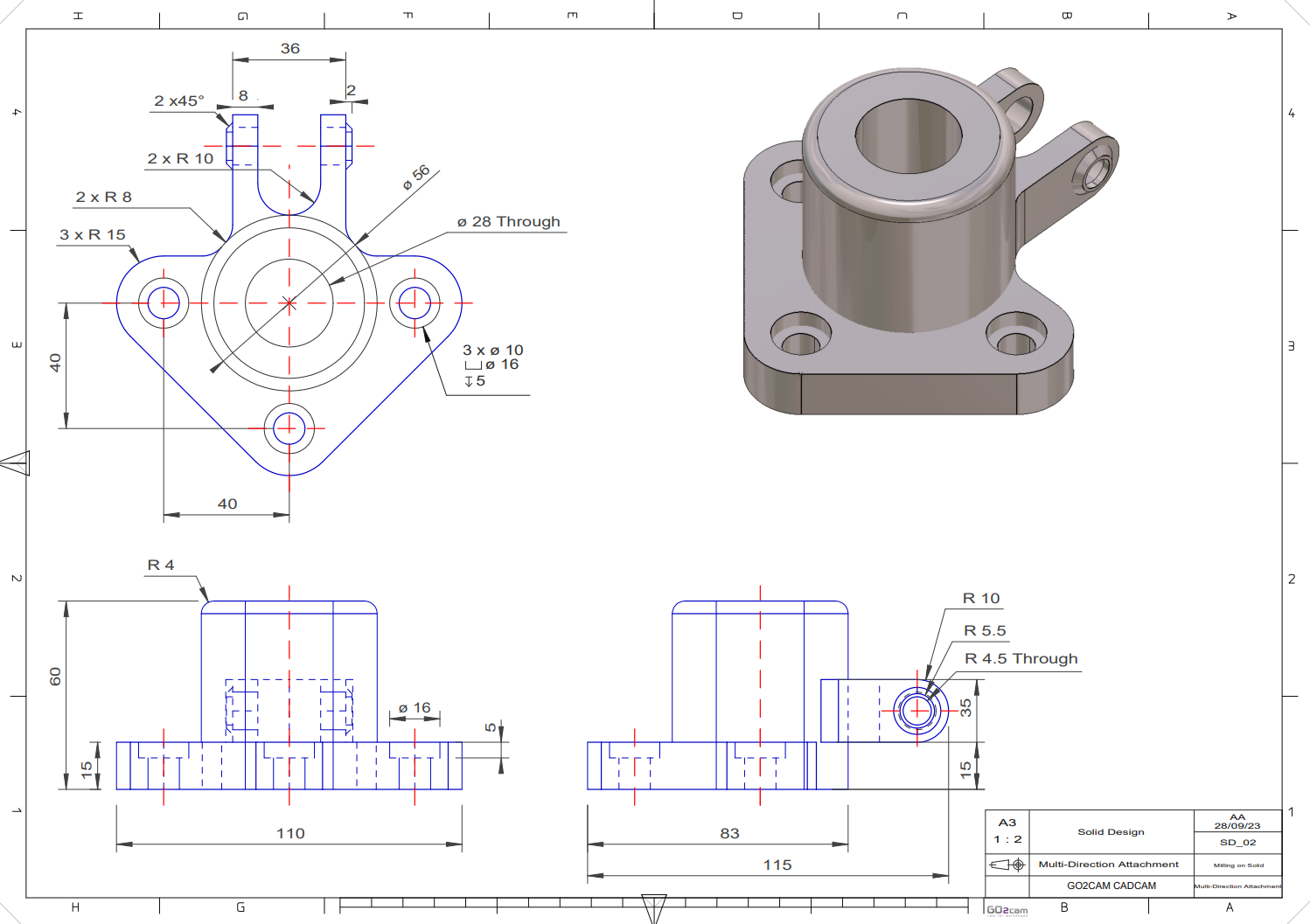
|
This video demonstrates creating a solid combined with a wireframe using these commands: cylinder, Boolean Operation, Plane on face, Solid Extrusion, Surfacic 
|