
|
|
List of new features and Improvements of GO2cam 2026, released on 2 March 2026. |
|
|
Icons used in the tables below |
|
New Features |
|
Improvements |
|
|
Web and Services
|
||
|
|
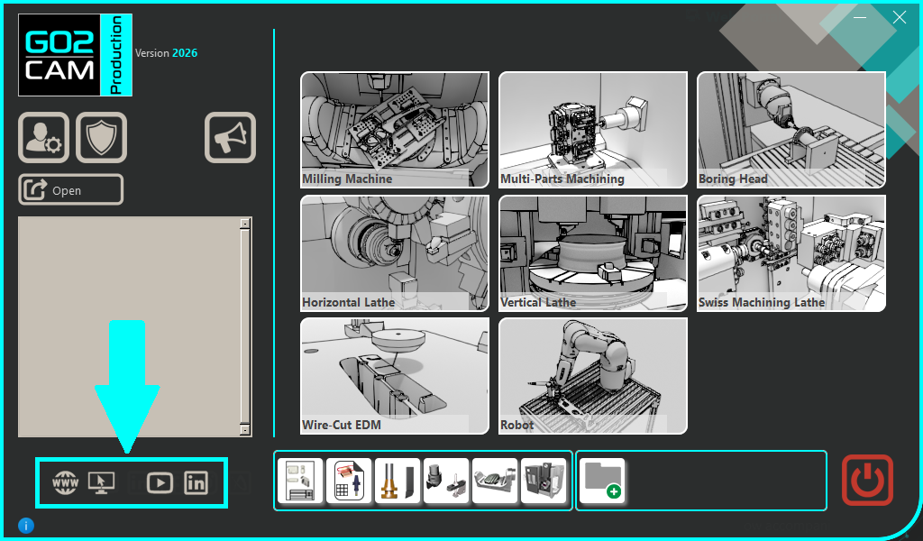
The new integrated Web Portal provides direct access to tutorials, documentation, and the GObot AI assistant without leaving the software. Users can instantly play "Tips & Tricks" videos and download JavaScript scripts to streamline their workflow. |

|
|
|
|
Graphic User Interface
|
||
|
|
Menus & Commands |
Reorganized menus and commands:
|

|
|
|
Theme |
Full Dark Mode: Visual comfort is optimized with Dark Mode now applied to all menus and tree panels. |
|
|
|
Ribbon Interface |
The New Ribbon Architecture
|
|
|
|
Software Configurations |
Dynamic Menu Scaling: You can adjust the ribbon size from small to large to suit your monitor and preference. |
|
|
|
A new See Only option appears in the elements popup via right-click. It displays only the selected part, feature, annotation, or entity. Deactivate See Only mode using the Cancel Hide option. |
|
|
|
|
You now have more flexibility when managing your workspace with two distinct toolbar options:
|
||
|
|
Speed up your daily tasks by creating your own keyboard shortcuts for any command that doesn't already have one. This new feature is easy to find directly within the Customize Toolbar window. |
|
|
|
|
GO2cam 2026.7 |
We added the Update command to the Customize Toolbar. It gives the ability to create shortcut to launch the computing update. |
|
|
|
Grid Display
|

|
|
|
|
Dialog |
|
|
|
|
Options |
The Tools > Options menu has been modernized and reorganized to help you find and manage settings more efficiently:
|
|
|
|
Facebook and Industry Arena links/icons have been removed. |
|
|
|
|
Web portal link has been moved and grouped with external links on the lower left. |
||
|
|
GO2cam 2026.6 |
The command ‘Add GO2cam File’ now recovers 5 axis expert cycles. But be careful to the axis defined in the cycle dialog, that may be changed while updating computing! |
|

|
Workflow
|
||
|
|
Complete redesign of the Import workflow:
|
This video is an example of the workflow in turning, demonstrating the most complete sequential operations. |
|
|
|
Fully Automatic Process: You can automatically obtain a machined part with all toolpaths, only with the import and automatic validation of the workflow. Everything is processed as per default/previously saved values. |
|
|
|
|
Workflow in Milling
|
|
|
|
|
Recognition of work-holding devices During the import workflow, solids can now be defined as work-holding device. This is taken into account on the part positioning step and also during toolpaths computation.
|
An example is given in the vertical turning module. |
|
|
|
Milling Turning Wire EDM |
Workflow for machined part The new command available in the File menu allows the launch of the import workflow of a machined part. The remaining stock is recognized and computation is carried out based on that. |
|
|
|
Milling Turning Wire EDM |
Workflow after Design The new workflow is not only dedicated to CAD files import; you can also draw and edit your part with wireframe geometry or solid models directly within the design environment and then start the Workflow.
|
An example is given with Solid Design. |
|
|
Workflow in Wire-Cut EDM
|
|
|
|
|
Import DXF Workflow
|
|
|
|
|
Creation of WAGs |
The new Workflow is also implemented in the environment of creation of Work-assembly devices. |
|
|
|
Geometry Generalities
|
||
|
|
The Manual Measure command have been completely reviewed with the following:
|

|
|
|
|
GO2cam 2026.4 |
Angular Holes Smart Turning Measure offers new information about angular holes: B and C angles values are given (in the Revolution Plane). 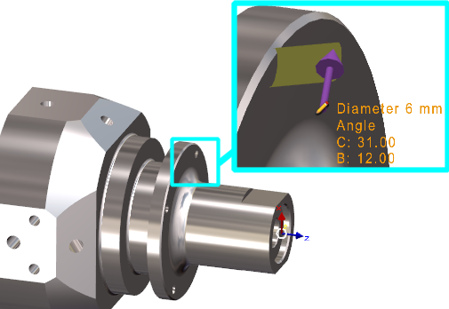
Values are also accessible and copyable in the information dialogue. |

|
|
|
A new Existing Stock checkbox has been added to the Nesting command dialog.
|

|
|
|
|
The Edit Element command now supports multiple text elements editions at once. You can select several text elements and any modifications you make will be applied uniformly to the entire selection. |
|
|
|
|
GO2cam 2026.6 |
Single Stroke Font When you install a single stroke font, it is not recognized as single stroke by default. To make it possible, we added an option in the Text Command, with a checkbox that must be set ON. |
|
|
|
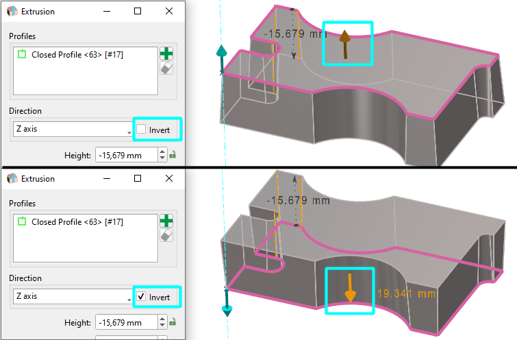
Solid extrusion |
Inverting the direction of solid extrusion can now be done by clicking a dynamic arrow on the screen. It is the same action as the button ‘Invert’ in the dialogue. |
|
|
|
Segment GO2cam 2026.7 |
We modified the behaviour of chaining option: From version 2026.7, chaining creation of segments is the default behaviour. Popup menu then enables to cancel the chaining and we can be back to chaining with the same popup. And also, the option chosen is now kept while being back to the Segment function. Reminder: previously, the popup menu enabled to cancel the chaining, but with no possible turning back. And the next time you came back to the segment was in Chaining option to ON. |
|
|
|
CAD Interfaces
|
||
|
|
A new tree for PMI analysis is accessible via the Measure function. A new PMI option is also available: Activate the PMI View, which aligns the workpiece view directly with the selected annotation. In addition, the menu options have been updated accordingly. |
|
|
|
|
SpaceClaim GO2cam 2026.4 |
Read of new SpaceClaim format scdox. This format is more recent and compressed than native format scdoc. |
|
|
|
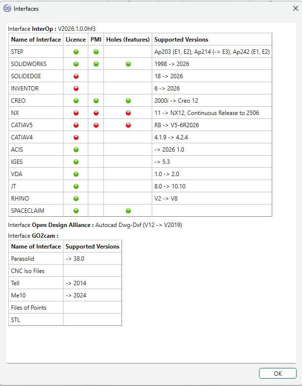
Some CAD interface versions have been updated:
|
||
|
|
The dialog box for the list of 3D interfaces, accessible through the Help menu and then About, has been reorganized in tabular form for better visualization. The dialog also shows available features for each interface (PMI, Hole). A green or red bubble indicates whether the feature is activated or not.
|
|
|
|
|
PMI Import performance have been improved. Faster reading and opening of files. Better fluidity in the manipulation of the part with PMI, especially rotation. |
||
|
|
Multiple Import GO2cam 2026.5 |
We improved the assignment of names while importing several files or single file with several solids. Previously, the name of solid defined in the CAD file had priority on the file name. Now:
Also the file name will appear only in case of multiple files import; if we import a file with multiple solids, no need to repeat the file name for each solid! |
|

|
Layout Design
|
||
|
|
|
|
|
|
|
Tooling
|
||
|
|
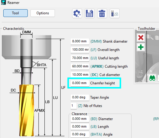
Reamer |
Chamfer height parameter has been added to reamer tools for milling and turning. This chamfer is taken into account for stock computing. As a consequence, a new strategy parameter: Depth calculation either by Tip or Diameter has been added for the Reaming operation. |
|
|
|
Interpolation |
New type of tool available for Interpolation: 1/4 circle mill cutter |
|
|
|
Tools Update GO2cam 2026.6 |
Tools Update Enhanced Any modification in Tool page (diameter value, coolant, specific number) generates modifications in the Technology page of cycles using the updated tool. For instance, cutting conditions are recomputed, coolant numbers are assigned, etc. |
|

|
Holes Features
|
||
|
|
|

|
|
|
|
|
||
|
|
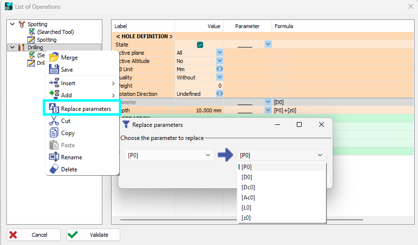
Search and Replace at Users Holes For list of operations, a new function is accessible in a tree pop-up for replacing parameters. |
|
|
|
|
Several hole-related dialog boxes have been fully rewritten in Qt, simplifying the internal source code; while they retain the same functionality and provide the possibility to resize the window. |
||
|
|
|

|
|
|
|
Machining Generalities
|
||
|
|
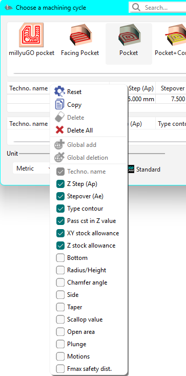
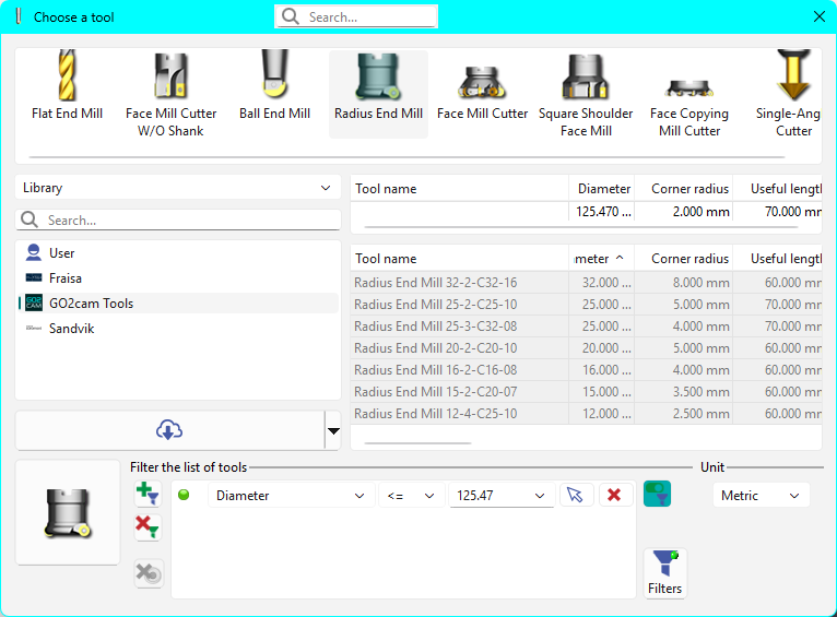
New Search bar within ‘Choose a tool’ and ‘Choose a machining cycle’ box to allow search for specific tool or machining cycles. 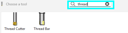
|

|
|
|
|
The default sorting of the list of tools shown as options is now diameter wise rather than name wise. |
||
|
|
Many improvements in the display of Machining Origins:
|
|
|
|
|
Cycle Selection The origins defined can be accessed during the cycle selection process in the dialog bar. Hence, the origin for each cycle can be directly defined at this point. |

|
|
|
|
New command that enables two types of Modifications of profiles:
|

|
|

|
|||
|
|
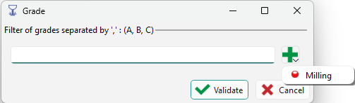
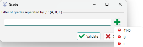
Automatically scan your existing machines and materials to dynamically generate and toggle entire grade categories within the selection dialogue. The list of existing machine and material grades are accessible in the dialog with the plus icon. |
|
|
|
|
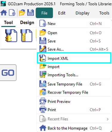
XML Tool Import: You can now open and import XML tool files within the Forming Tools and Tool Libraries, allowing you to modify them directly. |
|
|
|
|
Tools |
Chamfer height parameter has been added to reamer tools for milling and turning. This chamfer is taken into account for stock computing. As a consequence, a new strategy parameter: Depth calculation either by Tip or Diameter has been added for the Reaming operation.
|
|
|
|
Management of Collisions |
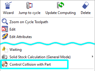
Test collision with Part (Machining Tree) This option had been greatly enhanced for version 2026, with a new engine more efficient and faster. It enables to control the collisions for all types of cycles (Previously, only holes machining and rapids were checked). It also means that computing may be a little longer and that cycles will be set into ‘warning’ more often, because potential collisions are detected more efficiently. For this, we decided to set the function OFF by default. |
|
|
GO2cam 2026.7 |
In version 2026.7, we decided to move the default back to ON. We also renamed this command ‘Control Collision with Part’ for greater clarity. |
||
|
|
GO2cam 2026.2 |
Multi axis linking between operations Linking between 2 operations using the same tool can be realized with a 5-axis simultaneous motion. For this, define a safety area (in Stock dialogue) and chosen ‘Follow 5Xs Area’ in the cycles strategy. 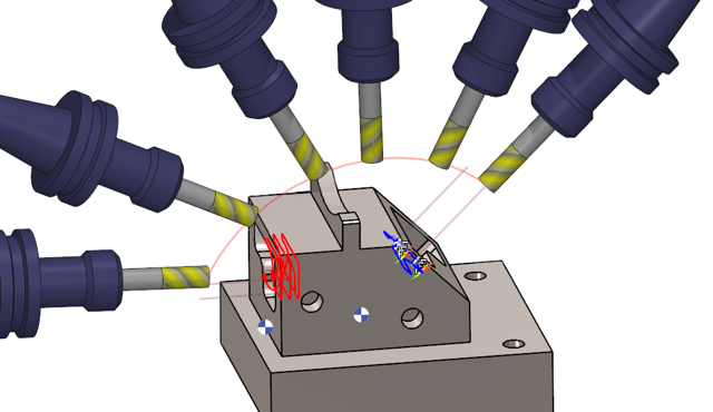
|

|
|
|
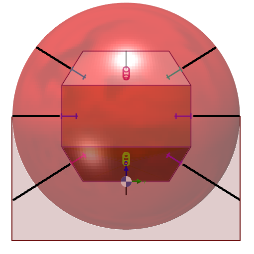
GO2cam 2026.5 |
The sphere mode is not anymore a full sphere but an hybrid shape with a half-sphere on top and cylinder on bottom. |
|
|
|
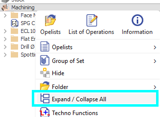
Expand/Collapse All has been moved from folder popup to the Machining popup. It is only available if folders have been created in the machining tree. |
|
|
|
|
All turning and milling cycles have a longer list of parameters customizable in the library columns. |
|
|
|
|
The elements of the libraries of tools and cycles are written in grey and the background is a lighter grey. |
|
|
|
|
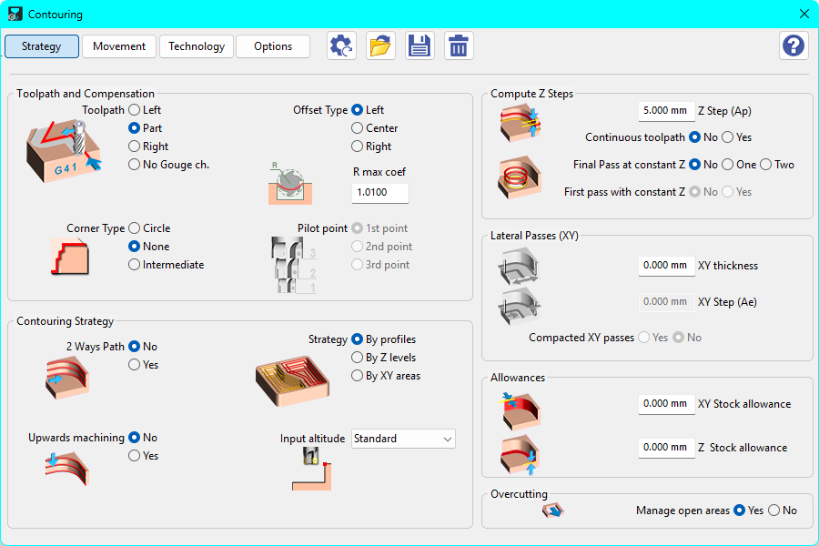
The Strategy dialog boxes are now larger with larger fonts and icons/images for better visual understanding. |
|
|
|
|
The Part/Stock comparison is improved with better computation algorithms. |
||
|
|
Opelist/Strategies
|
|
|
|
The Opelist has been reorganized into its own dedicated menu within the ribbon. 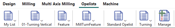
|
|
|
|
5-axis Opelist |
Create and standardize complex machining strategies by creating 5-axis expert Opelist. Click here to access the 5 axis Expert category and watch a video. |
|
|
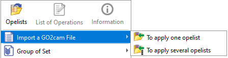
Import GO2cam File GO2cam 2026.2 |
The command that enables to import a PCE file to transfer the machining operations into opelists has a new behavior:
|

|
Simulation
|
||
|
|
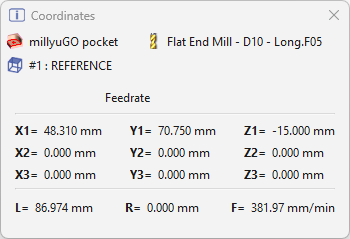
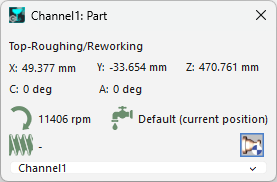
The coordinates dialogue is now easier to read, featuring bolded text and clear icons for key details.
|
|
|
|
|
Simulation GO2cam 2026.6 |
Form Tools We have improved the management of form tools in dynamic simulation. |
|
|
|
Simulation GO2cam 2026.7 |
Eccentric operations We improved general dynamic simulation performance for eccentric turn cycles. Please note this improvement is used only with Simplified Machining option active. |
|
|
|
Machine Tool Environment (MTE)
|
||
|
|
Clients can now instantly download and load machine kinematics (.mcb) by entering a specific ID provided by their VARs. |
|
|
|
|
Techno Functions:
|
|
|
|
|
You can quickly access and configure work-holding devices/WAGs by right-clicking the machine in the tree or the 3D window.
|
|
|
|
|
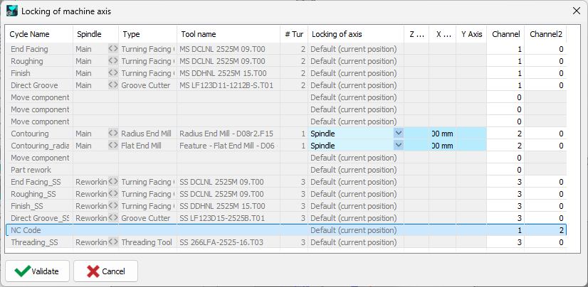
You can now change a toolpath's color directly from the synchronization Gantt chart, providing immediate visual feedback.
|
|
|
|
|
GO2cam 2026.4 |
Unreachable angles Since years, unreachable angles are displayed in red in the list of workplanes: we have added a warning for these unreachable angles. 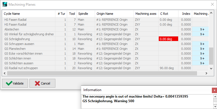
This warning gives you the delta angle value that must be set in the tool to allow the machining. The values can be copied in the dialogue and set in the tool position settings. |

|
|
|
Collision Tree The tree has been reimplemented in Qt, now supports search, and correctly respects the selected units instead of always displaying values in millimeters. |
||
|
|
Coordinates Window The part and machine origins are configurable, there are more tooltips on icons and buttons, the icons have been updated for dark mode, and the rotation icon now clearly indicates whether it affects the stock, the tool, or neither. |
|
|
|
|
|
|
|
|
|
A new field has been added in the machine numbering settings to allow you to start automatic tool numbering from a specified position. This enables you to reserve free positions in the magazine. |
|
|
|
|
In Turning and Swiss machining, the Gantt chart graphics have been renewed. It can be moved and it is resizable! |
||
|
|
Machining Features
|
||
|
|
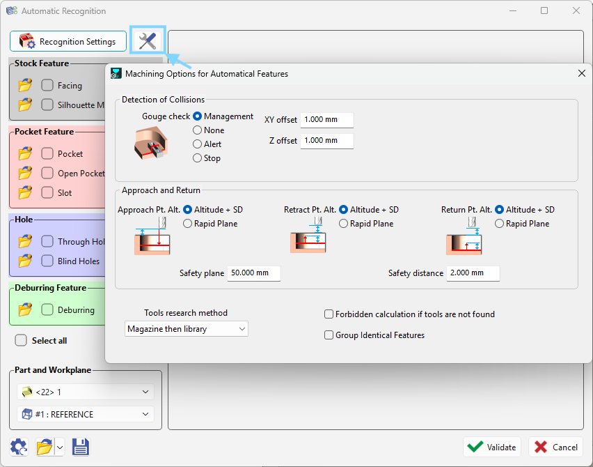
The Features Dialog now includes a new, dedicated dialog to manage Machining options, providing more direct control over how you configure and manage feature settings . |
|
|
|
|
2 Axis Milling & Shape
|
||
|
|
Access all machining pass parameters in one place with the new, easy-to-use dialog |

|
|
|
|
Users can now independently set First Pass and Last Pass Z-step depths for greater control. This update is available in millyuGO, Facing Pocket, Pocket, Pocket + Contour, Pocket Rework.
|

|
|
|
|
Vice and Clamps |
The completely revamped Vice and Clamps interface makes securing your parts faster and more intuitive. Key Features:
|

|
|
|
Interpolation |
A new plunging parameter has been introduced in Interpolation, adding an off-center plunge option similar to that used in threading. This parameter is located under Movement within the Strategy page, where values can be entered to adjust the off-center distance. |

|
|
|
Edges path mode of selection added for Standard cycle. This allows the selection of edges especially for non-linear and complex curved surfaces. |

|
|
|
|
Prepierced Holes |
You can now select solid edges directly when using the pocket function with prepierced holes. |

|
|
|
Reaming |
New Depth calculation parameter to tool end or diameter, as we can set chamfer for reaming tools. 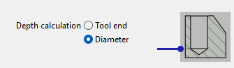
|
|
|
|
Chamfering |
Chamfering cycle has been improved to offer greater flexibility during tool positioning. Lead-in and lead-out arcs are no longer restricted to a 90-degree angle. |

|
|
|
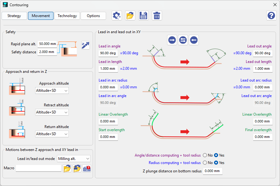
Contouring |
We’ve updated the Movement page with a new visual for Lead-In and Lead-Out options, providing a clearer preview of your toolpath transitions. |
|
|
|
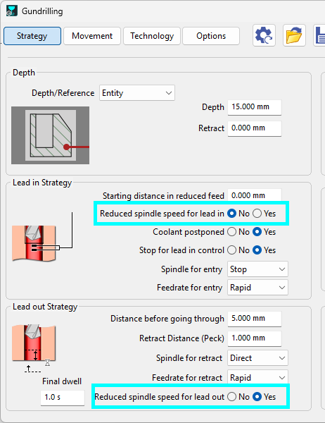
Gundrilling |
Two new parameters to the Gundrilling cycle that allow for reduced spindle speeds:
|
|
|
|
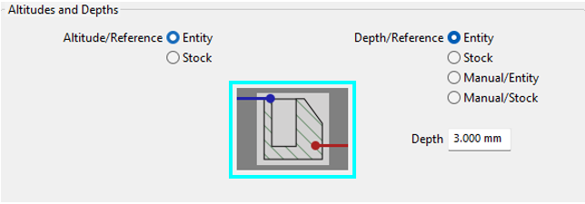
Holes |
We’ve updated the Altitudes and Depth pages within the Holes cycles with new icons. |
|
|
|
3 Axis Milling
|
||
|
|
3 axis Finishing |
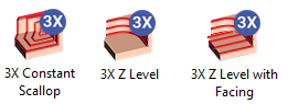
The 3-Axis Milling Pack now includes three new optional cycles. These additions are easily identified by a "3X" badge on their icons. |
|
|
|
The new multi-threaded 3X Z Level cycle significantly reduces computing time while offering optimized machining with integrated rework. |

|
|
|
|
New multi-threaded finishing cycle which delivers incredibly fast computing times and highly efficient machining for equidistant surfaces. |
|
|
|
|
3X Z‑Level with Facing is a hybrid strategy that combines Parallel and Z‑Level cycles to machine both flat areas and slopes in a single operation. |

|
|
|
|
Finishing Rework |
For the Auto Z Level, Auto Equidistant, Slope Z Level, and Slope Equidistant cycles, we have added an Optimized Toolpath option. When activated, this feature significantly reduces air time and unnecessary tool travel. 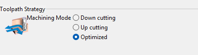
|
|
|
|
3X Spiral GO2cam 2026.2 |
Toolpaths computing In the page Options, we have added the ability to ‘Decompose the arcs of toolpaths’. This will generate G01 segments in NC file instead of G02/G03 arcs. |
|

|
5 Axis Expert
|
||
|
|
5-axis Opelist |
Opelists can now include 5-axis operations. Create and standardize complex machining strategies by creating 5-axis expert Opelist. |
|
|
|
Polyline Selection |
New Polyline Selection mode introduces a more intuitive way to manage geometry in multi-axis milling. |
|
|
|
Safety for 5X Expert GO2cam 2026.7 |
New behaviour for safety: if GO2cam safety plane is lower than the safety plane defined in the 5X cycle, we do not take it into account in NC file, as it is usually the case in other situation. |
|
|
|
Turning
|
||
|
|
Two new cycles for machining eccentric parts: Eccentric Roughing and Eccentric Finishing. 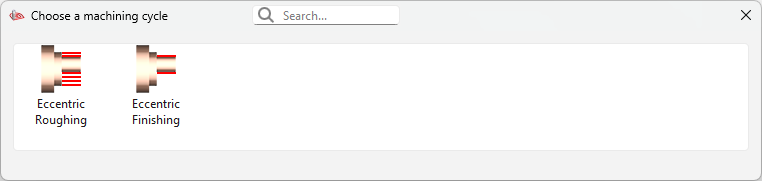
|
|
|
|
|
A new dialog box is displayed when adding a chuck to a part. A new Adjust option is also available via right-click on the stock, opening a dedicated dialog box. In addition, the chuck and jaws can now be modified while they are in use. |
|
|
|
|
The “Slice the Part” command is now available in the Horizontal Lathe module. |

|
|
|
|
GO2cam 2026.2 |
In the strategy, we added a new choice for the Pilot Point: Left, Center or Right.
|

|
|
|
A new strategy parameter is now available, called Retract distance at the end. It allows for a 45 degree from the stock wall, rapid retraction. A value has to be added by the user. the toolpath drawn will follow that distance. |
|
|
|
|
GO2cam 2026.4 |
New parameter Smoothing height that generates a smoother toolpath by avoiding 'subpockets' and wave-types toolpaths. |

|
|
|
Tapping cycle in Turning (Axial Hole menu) now offers two modes (Simple, Deburring), with Deburring adding Pass depth and Last pass depth parameters, and dwell options repositioned in the dialog. |

|
|
|
|
GO2cam 2026.6 |
We have added a new option ‘Tool Orientation’ I it enables to compute a different toolpath, since we can define the projection orientation of the form tool. It enables to accede to different areas of the profile, such as undercut areas. |
|
|
|
GO2cam 2026.5 |
The stock is now computed for a point to point operation. |
|
|
|
GO2cam 2026.7 |
Coolant parameter is now available in the broaching operation. |
|
|
|
Swiss Machining
|
||
|
|
GO2cam 2026.6 |
We have added a new option ‘Tool Orientation’ I it enables to compute a different toolpath, since we can define the projection orientation of the form tool. It enables to accede to different areas of the profile, such as undercut areas. |
|
|
|
New option in “Slice the Part”: you can now apply the section to all shoulders. |
|
|
|
|
Wire-Cut EDM
|
||
|
|
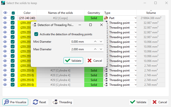
Automated detection and conversion of solid cylindrical components into threading points is possible during import via a dedicated dialog. A range of diameters can be defined for the detection algorithm.
|
|
|
|
|
Color Analysis
|

|
|
|
|
|
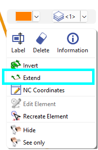
New “Extend profile” function in automatic profile selection to add custom lead-in, lead out, and corner radii to open profiles. The function is also available in the Design menu during profile selection, by right-click.
Watch an example video in machining generalities by clicking here to go to the category. |
|
|
|
GO2cam 2026.6 |
Download of Wires The Wires Library Dialog gives now access to the GO2tool library, with 14 libraries available for download. This is the exact same window than in milling and turning. |
|
|
|
Profile group optimization has been enhanced. The profiles are now automatically organized by proximity, starting from the lowest profile on the left |

|
|
|
|
Profiles in a group can be manually reorganized by drag and drop to change the cut order. |
||
|
|
|

|
|
|
|
Increased performance in recognition faces for 4 axis on solid with improvements in the recognition algorithm to better accept complex shapes. |
||

|
User Workshop Document
|
||
|
|
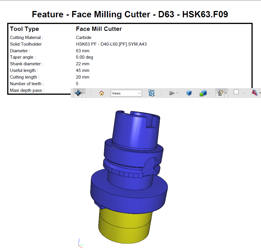
3D symbols are now exported to Workshop Documents. For instance, solid toolholders can now be seen in images displayed both in Standard Workshop Doc and UWD. |
|
|
|
|
GO2cam Mecanic
|
||
|
|
Automated detection and conversion of solid cylindrical components into threading points is possible during import via a dedicated dialog. A range of diameters can be defined for the detection algorithm. Click here to see a video available in Wire-Cut EDM category for an example. |
|
|
|
|
Strategies |
Color Analysis
Click here to see a video available in Wire-Cut EDM category for an example. |
|
|
|
Extend Profile
|
New “Extend profile” function in automatic profile selection to add custom lead-in, lead out, and corner radii to open profiles. The function is also available in the Design menu during profile selection, by right-click.
Watch an example video available in the Machining Generalities category by clicking here. |
|
|
|
Profile group optimization has been enhanced. The profiles are now automatically organized by proximity, starting from the lowest profile on the left Click here to see a video available in Wire-Cut EDM category for an example. |
||
|
|
Profiles in a group can be manually reorganized by drag and drop to change the cut order. Click here to see a video available in Wire-Cut EDM category for an example. |
||
|
|
Multiple Parts Machining
|
||
|
|
JavaScript |
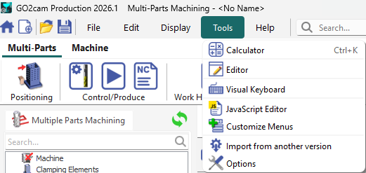
The MPM module now supports JavaScript. This functionality can be found directly under the Tools menu. |
|
|
|
GO2cam for SolidWorks
|
||
|
|
Ribbon |
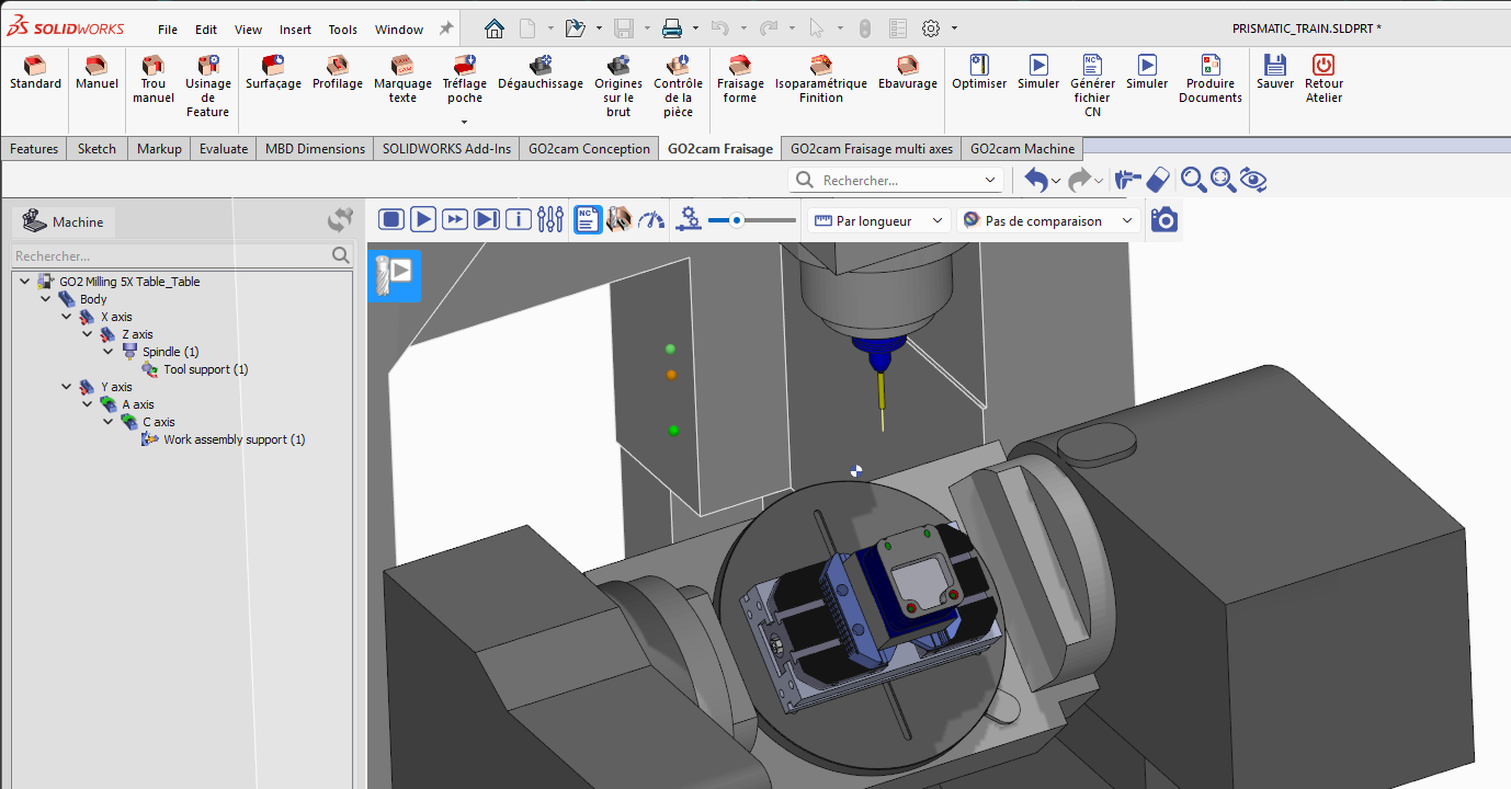
Modernized Navigation: The traditional menu system has been replaced with a Ribbon interface, featuring larger icons. |
|
|
|
GO2cam Designer
|
||
|
|
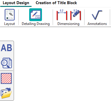
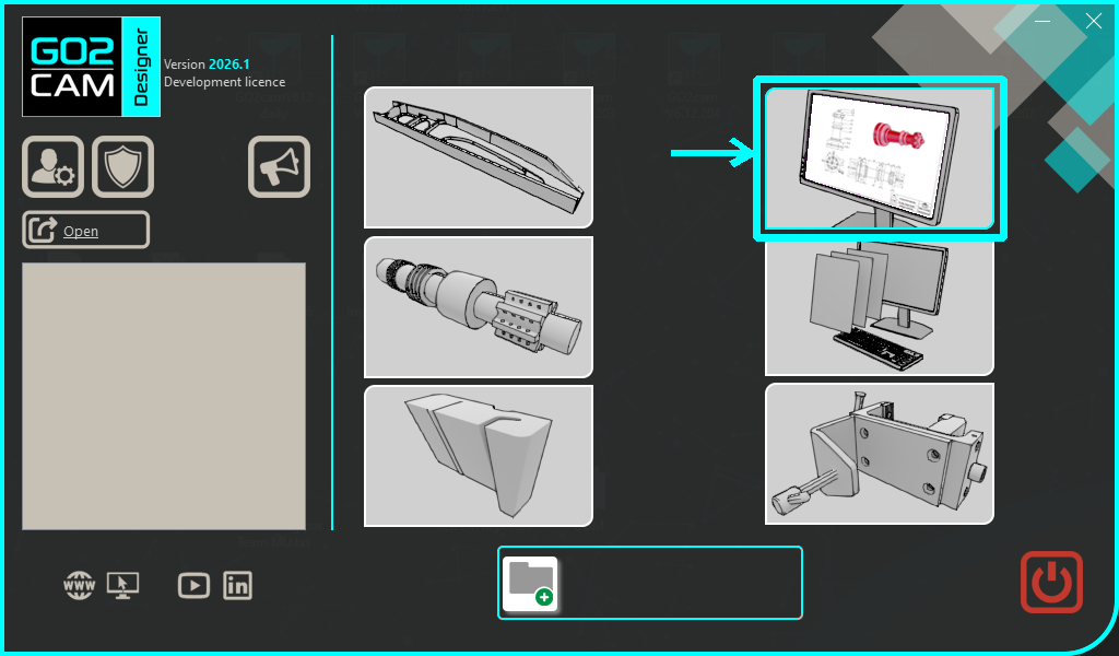
Layout Design |
Access to the Layout Design environment is now available on the Homepage. |
|
|
|
External Links
|
|
|
|
Ellistat JS Macro |
A dedicated JS Macro has been developed, that enables a direct connection between GO2cam and Ellistat. This integration allows you to export your machining data including cycles, tools, and CAD models directly to the Ellistat 3D platform for advanced analysis and inspection. |
|
|
NC Simul |
For MPM, multiple part exports to NC Simul is now possible. |
|
|
NC Simul |
NC Simul export now also includes solid holders. |