

|
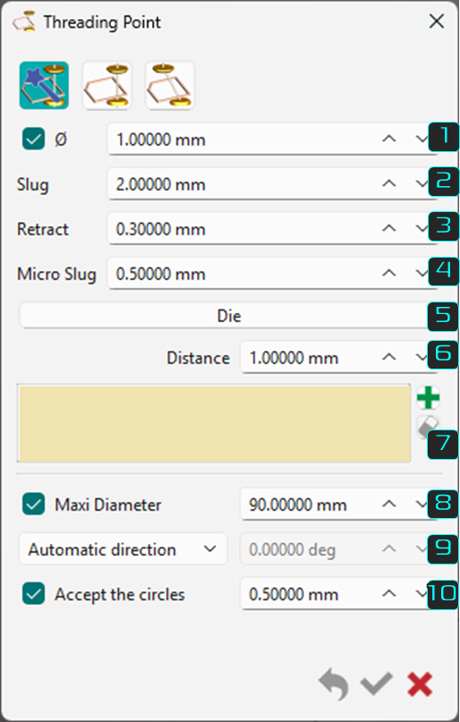
This function is the preparation step before machining. It defines useful machining information such as slug, micro slug values and retract between passes. The creation is linked to a profile analysis and is very fast with a selection box if you have many profiles to machine. |
Presentation
|
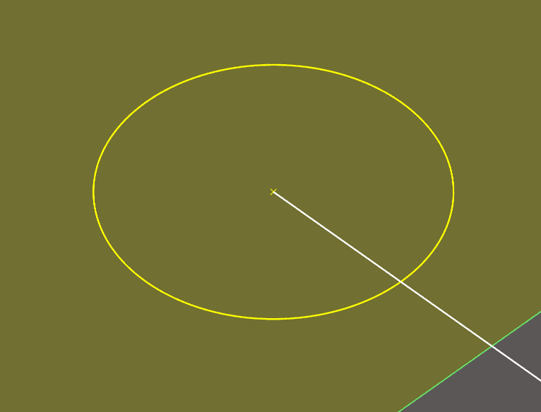
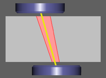
The threading point is a wireframe entity represented by a point and a circle in GO2cam. It defines where the wire enters and exits the material. Although a wireframe entity, threading points are distinct from geometric points in the filter dialog. A dedicated icon/entity is available as shown below: 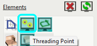
|
|
|
|
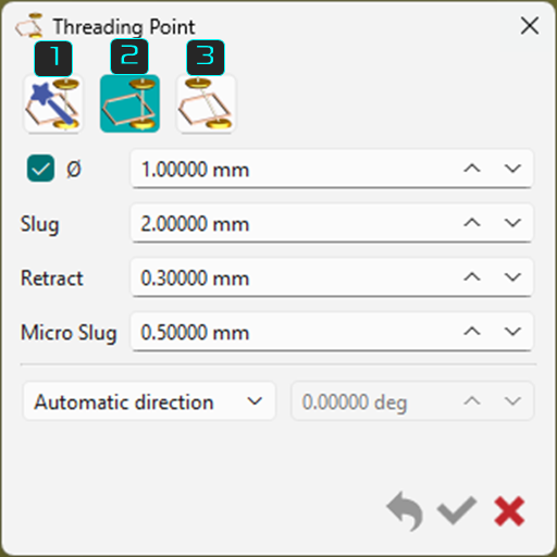
Three threading point definition methods are available in a single dynamic dialog. Icon buttons on the top left represent them, and their specific settings appear or disappear based on the selected method. The three methods are listed below, with details for each discussed further on this page. |
|
|
|
|
Auto threadings on profiles |
|
|
|
Manual threading |
|
|
|
Inclined threading |
|
|
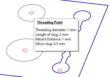
When you create Threading points, the information is given into a balloon while passing the mouse over the threading point. The display does not interfere with the other elements. |
|
|
1. Auto Threading on Profiles
|
Automatic threading is useful for many shapes and works for the majority of closed profile cases. The threading point is created automatically along the longest element of the profile and normal to its middle point. If points exist in the CAD model, GO2cam recognizes them as threading locations with automatic threading. |
|||
|
|
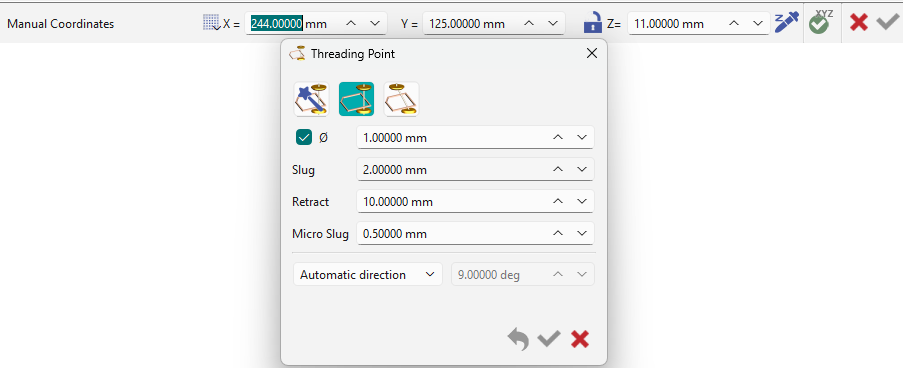
Threading point diameter. Enter the diameter of the threading point. If the box for the diameter is unchecked, a point entity is generated for the threading point. |
|
|
|
|
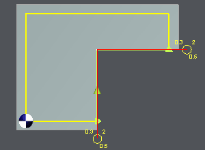
Definition of the slug for night and day strategies. This distance is the material left when partial passes are programmed. In night strategies, the slug (larger value 2) is defined to ensure the rigidity of the part and the quality of machining. All partial passes are done at night while keeping the slug value and a stop is automatically programmed in the strategies. The finishing passes are completed in the morning. |
||
|
|
Retract: motion of the wire programmed between each pass defined in the strategy. This distance avoids leaving a mark on the part. |
||
|
|
Definition of the micro slug for night and day strategies. Micro slugs are smaller values compared to Slugs, to maintain the part but essentially work the same way. The location of the micro slug changes regarding the number of passes, either odd(see image on the right) or even (see image above) number. The machining strategies enable to manage this case. Please read the chapter Toolpath Type. 1 - Offset distance 2 - Slug value 3 - Micro slug value |
Even Passes (2, 4, 6 passes etc.): 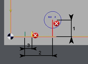
|
Odd Passes (1, 3, 5 passes etc.): 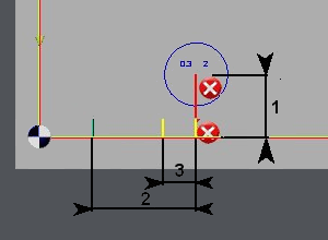
|
|
|
Choose between die or punch. Click on the button to switch between Die and Punch. This gives the location of the threading point inside or outside of the selected profiles. |
|
|
|
|
Offset distance. This distance value defines the offset of the center of the threading point to the profile (typically the longest element of the profile). |
||
|
|
Selection box Lists the profiles selected and allows to add or delete from the list. |
||
|
|
Maxi diameter This is used for circular profiles. For profiles below or at the set value, the threading point is generated based on the offset distance set. For profiles above the set value, the threading point is on the center of circular profile. |
||
|
|
Angular direction of machining from the threading point to the profile 3 modes are available in the drop-down: Automatic direction - typically perpendicular to the longest profile element. Forced only on circles - the forced angle of attack is applied only on circular profiles. Forced on all shapes - the forced angle of attack is applied only on all profiles. |
||
|
|
Accept the circles Checking this parameter allows to set a constraint for circular profile selections as per the defined value. Circular elements below the defined value are not considered as profiles for threading point selection. All circular elements from the value defined and above have threading points generated. |
||
|
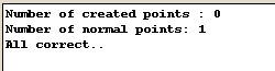
When validating, the threading points generate, and a message at the bottom confirms their creation. If creation fails, the message explains the reason. For example, a 4 mm offset is impossible for two small shapes. Adjust the offset or create points manually. |
|
||
Geometrical Creation
|
The examples below demonstrates 2 cases of the use of automatic threading. |
|||
|
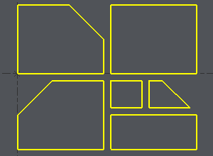
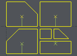
Example 1 : Only the wireframe shapes of multiple profiles are provided. GO2cam analyzes the profiles and creates the threading points for each, based on the set parameters. In this case, a 4mm offset is defined but it is impossible for the two smaller shapes, which must be adjusted or have threading points created manually. |
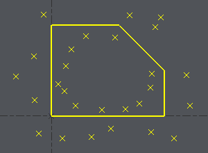
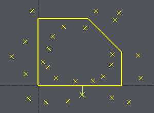
Example 2 : For this case, the draft has multiple points with a single profile. GO2cam analyzes the profile and selects the point that best matches the entered parameter for threading.
|
||
|
|
|
|
2. Manual Threading
|
The manual threading is often used in case of machining an open profile, where you need to create 2 points, or in case of 4 axes machining where automatic threading is not recognized. |
|
|
|
|
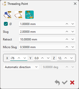
Dialog box The available parameters in the dialog box are limited but similar to the automatic threading on profiles. The only difference here is the manual placement of the threading point on the profile. Give the location of the point by entering its coordinates in the ribbon or by clicking a point on the screen. If needed (check the box), enter the diameter of the threading point. Most of time, the manual threading point is outside the material so it is not necessary to create the diameter to machine it later. |
|
|
Selection in Machining: In the machining selection, use the Approach and Return icons to declare the threading points. |

|
3. Inclined Threading
|
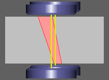
Inclined threading is mostly used if the shape to machine does not allow creating vertical threading. The general technological parameters are defined the same way as other threading points. The creation of inclined angle is defined through a vector, by clicking 2 points or inserting the values in the available field.
|
|
|
|
|
|
Other Cases
|
|
Threading Point Detection During Import GO2cam can automatically detect small, solid cylindrical components as threading points and convert them as such. This is available during import via a dedicated dialog. Access to the dialog is available through the Threading button at the bottom of the box.
|
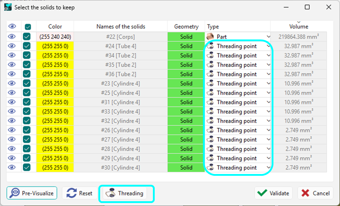
|
|
The checkbox for 'Activate the detection of threading points' must be activated to implement the detection algorithm. A range of diameters can also be defined to limit the detection range. 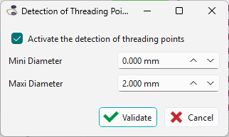
|
Watch a video below showcasing the detection algorithm during import.
|
|
|
Threading point in pocketing cycle The threading point is taken into account by the pocketing cycle which considers it as the pre-pierced hole to avoid automatically. |
||
|
Recovery of threading points for DXF import
|

|
|