
Presentation
The multiple import feature involves selecting several CAD files simultaneously, or one file that contains multiple solids.
The procedure remains consistent across both scenarios, and the same approach is applied whether we are dealing with turning, milling, or wire EDM.
The steps mirror those of a standard automatic import; the only difference is an added initial step: processing the list of solids presented in a table.
Typically, two main scenarios arise when importing multiple solids:
-
Importing an assembly
-
Importing a part along with its stock.
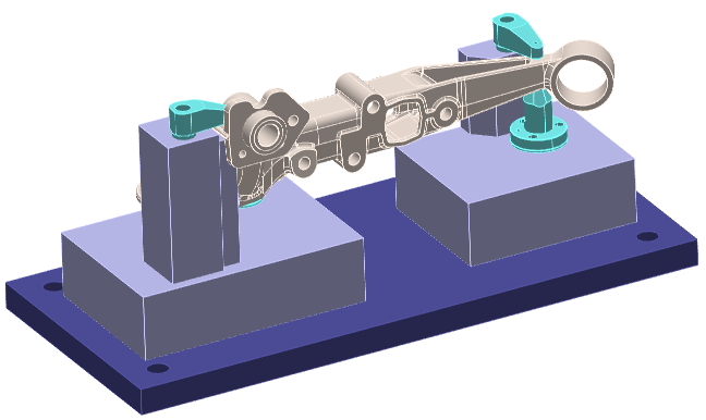
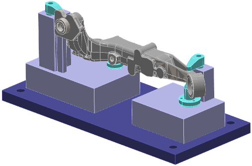
The following example illustrates a typical imported assembly file.
|
|
|
|
|
Recognition of work-holding devices During the import workflow, solids can now be defined as work-holding device. This is taken into account on the part positioning step and also during toolpaths computation.
|

An example is given in the vertical turning module. |
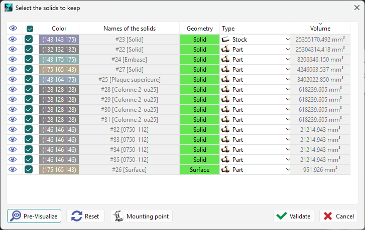
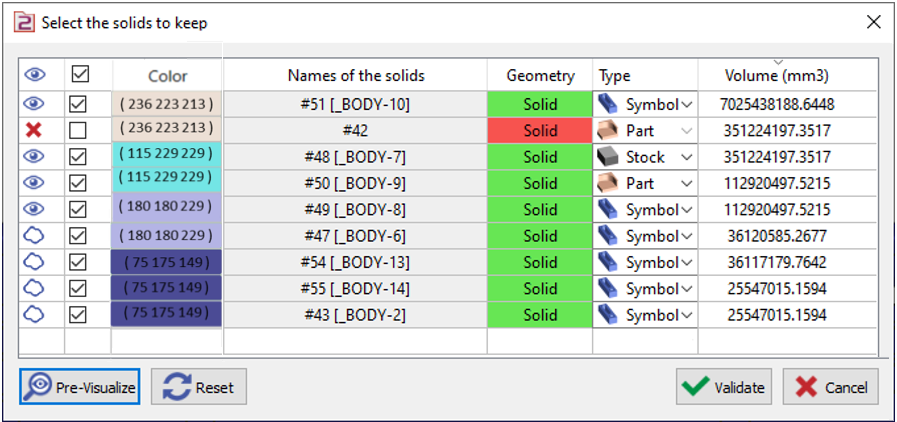
Exploring the table
Each row in the table represents a solid. These solids are arranged from largest to smallest, and the volume in cubic millimeters (mm³) is displayed in the final column. Selecting a solid on the screen will automatically highlight the corresponding row in the table.
The cells offer multiple actions to help prepare the file:
|
|
Visibility |
Clicking this icon toggles a solid’s visibility. Even when hidden, the solid remains selected for import if the validation step is performed at this point. |
|
|
|
Selection for the import |
The checkbox is selected by default, meaning all solids are queued for import upon validation. If you uncheck a solid, it will be excluded from the import.
Red Cross icon appears in the Visibility column, indicating the solid has been removed from the import process. |
|
|
|
Color of the Solid |
A new “color” column now displays each solid's color when importing multiple files. This is especially useful for distinguishing which solids to preserve, and the color code is also shown. |
|
|
|
Names of the Solids |
The solid name used to have priority to the file name; not anymore. Here is the new behavior:
Other change: the name of file appears only in case of multiple files import. It will not appear if we imported one only file with several solids; no need to repeat the file name for each solid. |
|
|
|
Geometry |
This column indicates the geometric type—solid, wireframe, or surface. The cell background color reflects the element’s quality: green means the element is correct, while red indicates a detected issue. You may either repair the element after import or exclude it now if it isn’t necessary. |
|
|
|
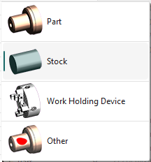
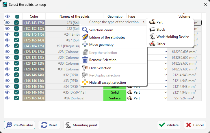
Type |
The goal here is to specify how this element will be used later in GO2cam. The cell provides four options: Part: define the solid as a component to be machined. Stock: automatically convert the selected solid(s) into machining stock. Work Holding Device: specify elements used for work-holding and clamping. Other: designate a solid that does not belong to any of the first three categories. When creating the automatic stock, this element is excluded from the bounding box calculation. For example, an origin point is sometimes modeled as a solid. You can choose the type for each solid individually, which is common for parts and stock. It is also possible to select multiple solids at once and then use the popup menu to assign their type. Further details are available on the next page. |
|
The buttons, at the bottom of the table, enable general actions:
|
|
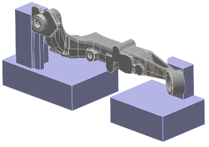
Pre-Visualize: reverses the hide commands, allowing you to view the elements that will be included in the import. |
|
|
|
Reset: all prior actions—such as hiding, selecting, or changing element types—are undone and restored to their original state. |
|
|
|
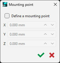
Mounting point: Clearly indicate the precise location where your workholding device should be mounted. |
|
|
|
Validate: After the treatment finishes, click the validate button to proceed to the next step. |
|
|
|
Cancel: Pressing this button exits the automatic import process. Note that the import itself is not terminated; the solids are still imported, but they will not undergo any positioning, stock allocation, or origin creation. |
|
Clicking on the Headers also triggers several actions, listed from left to right:
-
Toggle visibility or invisibility of all elements simultaneously,
-
Cancel or confirm actions for all elements at once,
-
Sort elements by solid names,
-
Sort elements by geometry type,
-
Sort elements by element type,
-
Sort elements by volume, either in ascending or descending order.
Example of treatment and videos
|
This assembly contains the component along with its cast stock and several clamping mechanisms: The second solid, which is the dark blue plate, is incorrect and considered unnecessary; therefore, it has been removed from the import. The four clamping elements are currently hidden. Each element has been classified with the appropriate type: ‘Part’, ‘Stock’, or ‘Symbol’. The part and its mounting device are now prepared for machining. |
|
|
|
|
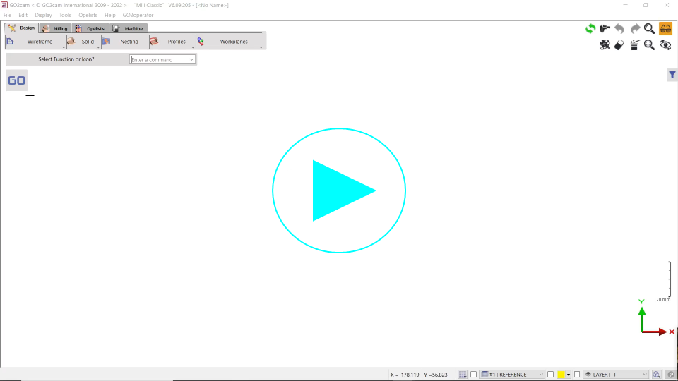
▶️ Here is a video on Multiple Solid Import:
|
▶️ Here is a video on Assignment of Solids:

|
Popup Menu
|
Right-clicking on one or more lines opens a menu that offers several actions, allowing you to manage multiple selections at once:
The menu also includes options to delete and hide objects. |
|
|
▶️ This video shows how the ‘Move’ command can be used while importing multiple CAD files: 
|