
Introduction
PMI is very important especially in digital inspection. It is defined as any non-geometric data included within a 3D CAD file. PMI normally includes data such surface profiles and tolerances. An advantage can be that instead of relying on 2D drawings to convey engineering data, it can be embedded within the original CAD file. PMI is an optional module.
|
|
PMI Import performances have been improved. Faster reading and opening of files. More fluid manipulation of the part with PMI, especially rotation. |
|
CAD formats with PMIs
Here is the list of CAD formats that includes PMIs:
-
*.CATPART (CatiaV5)
-
*.PRT (NX)
-
*.PRT (Creo)
-
*.SLDPRT (SolidWorks)
-
*.JT
-
*.STEP (AP242 only)
Inventor and SolidEdge can also manage PMIs, but GO2cam cannot read them in the native files formats; you should export in STEP AP242 to read them.
Process in GO2cam
|
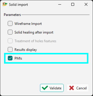
Import To read PMI features in GO2cam, the checkbox for PMIs must be enabled in the import dialog.
|
|
||
|
The following can be done with the PMI features from imported solid files (any format):
|
|
||
|
|
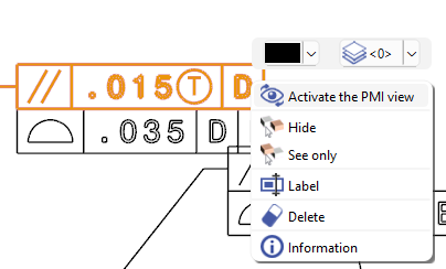
A new PMI option is also available by a right-click on an annotation: Activate the PMI View. This reorients the workpiece view such that the selected annotation is normal to the screen. |
|
|
PMI analysis and Options
|
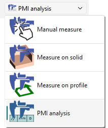
In measure, the option PMI analysis can show the faces concerned for each dimensions selected. |
|
|
|
|
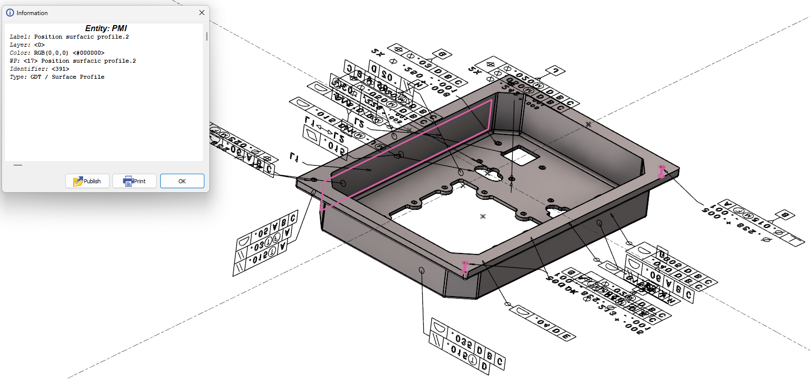
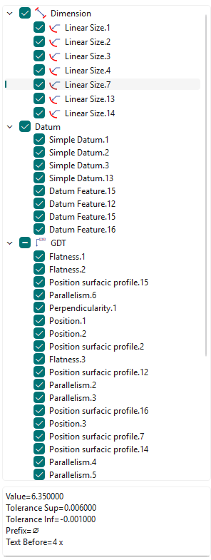
A new tree for PMI analysis is accessible via the Measure function. The PMIs in the tree are gathered by type (Dimension, Datum, GDT,...). Semantic information are also available at the bottom of the tree for a selected PMI. Watch a video below showing the Activate the PMI view option and the new tree. 
|
|
|
You can run the measure between two solid faces to modify the value. This only works for annotations of distances and diameters. |
||
|
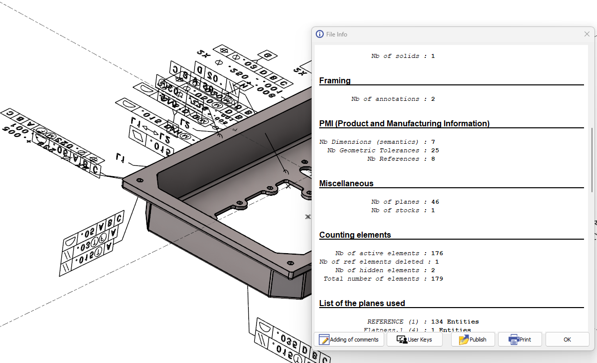
Types of PMIs is availalbe in ‘File Info’ The detail of the number of PMIs by type is given: Nb Dimensions (semantics)
Editing dimension does work only with Dimensions (semantics) |
|
|
Note: PMI can also be managed in the Control command: click here for more info.