
This command enables to measure and modify elements and to get information about any type of element, at any time.
Four modes of use are available:
|
|
Manual measure |
|
|
Measure on solid |
|
|
Measure on profile |
|
|
PMI analysis |
These modes are contextual: if there is no solid in the part, the dynamic measure does not appear in the command. But if there is one or several solids, the dynamic measure is the default mode of the command.
|
|
Measure is now accessible with shortcut Ctrl+m. |
The manual measure
The manual measure offers two types of information:
-
a measure between two elements
-
information about the characteristics of the element
Measure between two elements
|
It can be done in: wireframe geometry, solid corner, machining stock, toolpath. Several measures are displayed on the screen and in the information window, according to the selection done in the dialog area:
|
|||
|
|
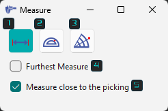
A new dialog box with three measurement states and two options are available: |
||
|
|
Measure distances: Used for measurement of linear distances between entities. |
|
|
|
|
Measure angles: Used for angular measurement between entities. |
||
|
|
Measure distances and angles: Used for combined linear and angular measurements. |
||
|
|
Furthest Measure: Snaps and provides the largest linear distance between selected 2 entities. Only available for linear measurements. |
||
|
|
Measure close to picking: Snaps and provides the smallest linear distance between selected two entities. Only available for linear measurements. |
||
|
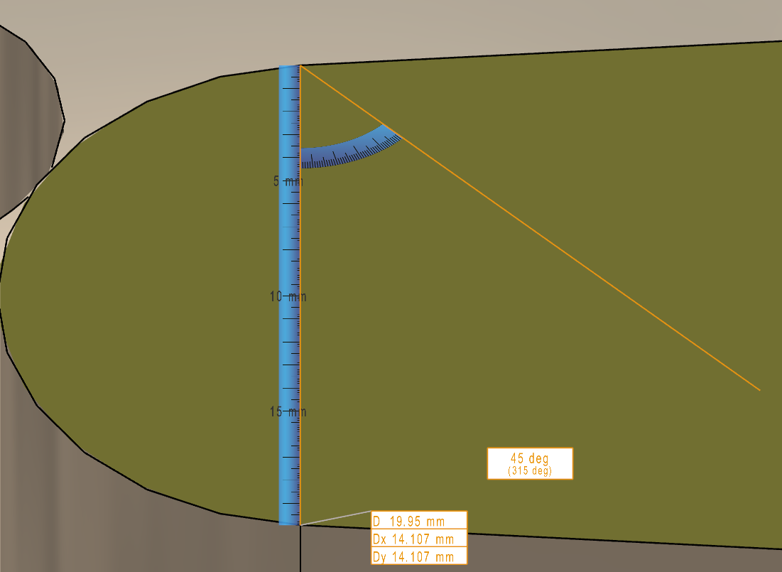
A new dynamic ruler is now available for manual measure. This improves the visual clarity when reading dimension. This ruler’s graduations auto-adjust, scaling with the zoom level. |
|
||
|
▶️ Watch a video on the right demonstrating the novelties listed above in manual measure. 
|
|||
|
Measure of 2D geometry taken from a DXF file: 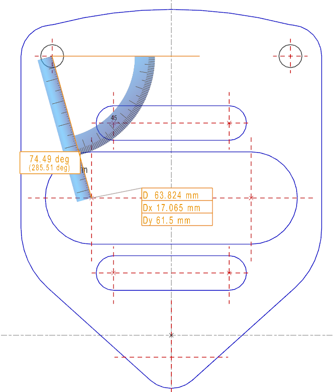
|
On a solid, you can get values that measure on solid cannot find: here, the position of the hole center according to the edge. For this, click the center of hole and then the solid corner. 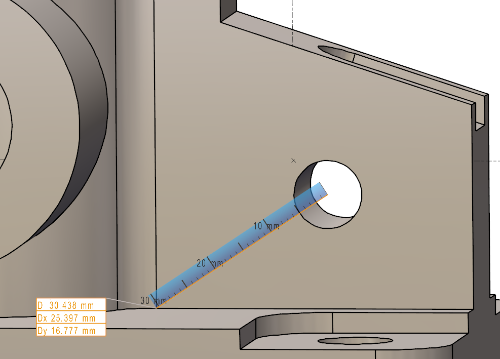
|
Information about the characteristics of the element
For this, double click the element on the screen. The information obtained are different according to the type of element selected. For example, for the linear geometric elements (segment, line), GO2cam displays the positioning angle in the plane XY and the length of segments.
The measure on solid
The dynamic measure has three purposes:
-
measure distances and angles on the solid faces
-
modify the measured values (in accordance with the solid topology)
-
give tolerances to the measured values
Measure distances and angles on the solid faces
This action is applied on the solids and on the machining stock. This enables to click faces and to accede to a great number of modes of measure.
Symbols can also be selected. So, you can measure a distance between stock or part and vice or clamps for example!
|
For the measure on solid mode, the list of options is displayed in a combo box with a self-explanatory diagrams and the number of clicks required for the action. Find some examples below:
|
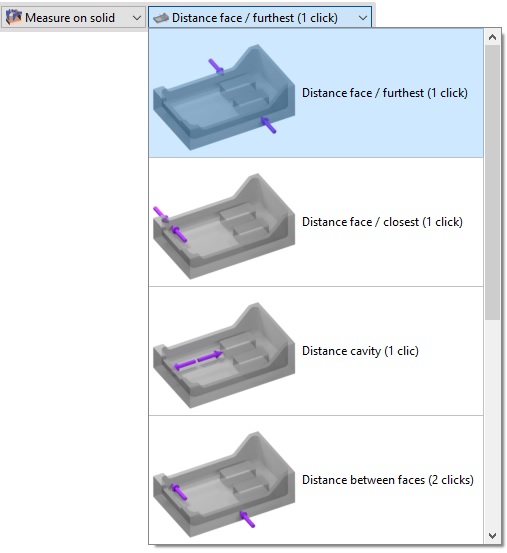
|
|
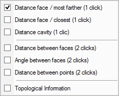
The options can also be accessed by right-clicking on the background after selecting the control command. |
|
|
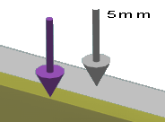
Display: purple arrows are displayed to indicate the selected faces. When the stock is selected, the arrow appears in grey. Measurements can then be taken between the solid part and the stock to determine, for example, the amount of material to be removed. |
|
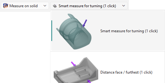
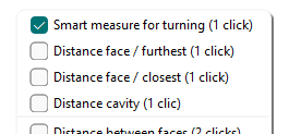
Smart measure for turning
|
This options is only available in the turning module. It allows for smart measurement of multiple features of a cylindrical part quickly and easily. It can recognize diameters, radii, fillets and angles automatically. |
|
|
|
|
|
A new feature allows the recognition and quick measurement of B and C angles of holes with the Smart measure. Simply select the angular hole to obtain its diameter and the angles instantly. The angle values are also displayed in the information box and can be copied from there. 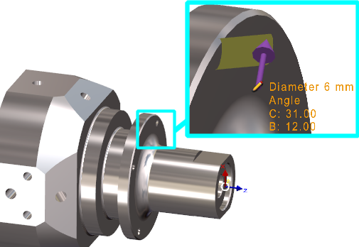
Watch a video on the right showing how it functions. |

|
|
Topological Information
|
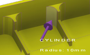
This mode is not really a measurement but enables to obtain information about the solid faces. Move the cursor on a face and it will display its type (plane, cylinder), the orientation (vertical, horizontal, taper…) and sometimes a value (radius, angle,…). This command can be used both in the design environment and in the machining menus when selecting geometry or tools. The information provided can assist, for example, in selecting the appropriate tool.
|
|
|
Table of topological information:
|
Type of face |
Information displayed |
|
Plane |
Vertical, Horizontal, Taper, Undercut |
|
Cylinder/ Face |
Radius |
|
Holes |
Radius + angle if conical |
|
Cone |
Angle, maxi radius and mini radius |
|
Torus |
Radii |
|
Bspline / Iso Surfaces |
Mini curvature radius |
Use
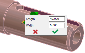
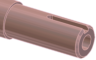
When you select a measure mode and click the face(s), the value is displayed on the screen. If a ‘pencil’ symbol appears, click it to enter a Rapid Edit menu, where the value can be modified.
|
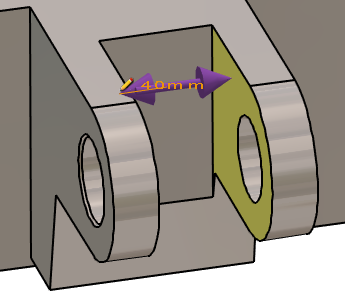
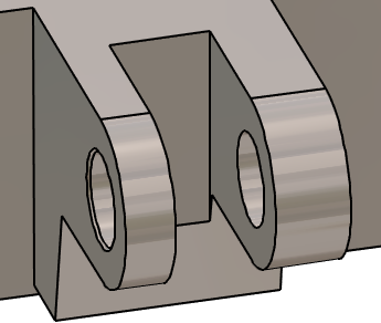
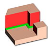
The measure between the two arms of the clevis gives the value of 40 mm. The measure mode used is ‘Distance Cavity’, with one click, but it could have been ‘distance between faces’. Clicking the dimension opens the RapidEdit box for modification. |
Then enter 32 mm. The button on the right shows a single arrow. It means that the modification is applied in one direction, according to the face clicked. (or first face clicked in case of ‘measure between faces’). |
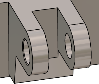
By clicking the button, a double arrow is displayed and the modification is applied symmetrically.
|
|
|
|
|
▶️ Watch a video how to use the control command to modify values:
|
Features
-
Those options are contextual, they appear according to the mode of measure and the selected element:
-
One side/Both sides: as explained above, apply a modification in one direction or symmetrically.
-
Selection of similar faces: this option enables to repeat the actions from the current element to all the identical elements! If a hole or a groove is modified or assigned a tolerance in turning, this command can be used to apply the same change to all similar geometries.
-
Chained fillets: this option gives the possibility to modify the radius of a fillet and to all the tangent fillets.
-
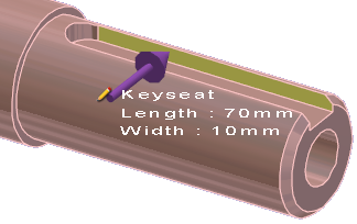
Elements: while using the mode ‘Topological information’, some elements are directly recognized as their type not geometry, such as the Holes and the Keyseats in turning
|
|
|
Tolerancing
With the same process, you can apply tolerances to some values. Let’s take the example of a 6g6:
-
If the tolerance g6 is entered, the average value is applied: 5.992.
-
If g6- is entered, the lower value is applied: 5.988.
-
If g6+ is entered, the upper value is applied: 5.996.
-
A tolerance interval may also be specified. For example, 6IT(-0.15, +0.05) applies the average value: 5.95.
|
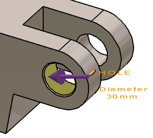
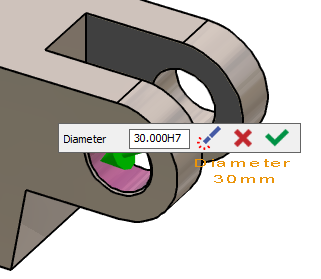
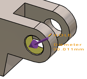
The hole diameter is 30 mm. |
Apply H7 tolerance. |
The average value is applied to the geometry: D30.011 mm |
|
|
|
|
▶️ This video shows one of the major strengths of GO2cam regarding the solid editing and specially tolerancing in milling: 
|
▶️ Watch a video on modification and tolerancing on turning solid: 
|
The measure on profile
This command enables to control the profiles and obtain some important information.
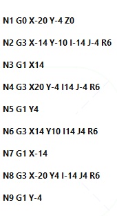
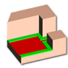
First create a profile with a bounding box or by defining the starting and ending elements.
Once the profile is created:
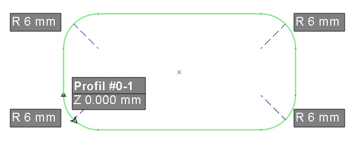
Some information are displayed on the screen, on the profile: profile number, Z altitude, values of radii.
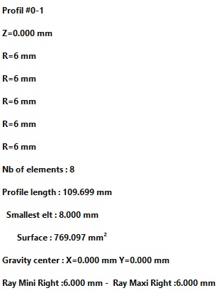
Many information are displayed in the Information Window:
-
A simplified iso enables to obtain the calculation of toolpaths,
-
The main characteristics of the profile: number of elements, length, mini radius, maxi radius, etc.
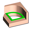
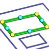
Simplified Iso:
Main characteristics of the profile:
The access to the different modes for the measure on profile option is available through the combo box in the dialog area. The different modes available are:

|
Automatic |
|
Silhouette Pocket |
|
Bottom Face |
|
Lateral Face |

|
Silhouette |
|
Wireframe |
|
Profile |
|
|
PMI analysis
|
|
PMI Import performances have been improved. Faster reading and opening of files. More fluid manipulation of the part with PMI, especially rotation. |
|
|
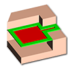
GO2cam is also able to read PMI from CAD files. In Control, the option PMI analysis can show the faces concerned for each dimensions selected. |
|
||
|
|
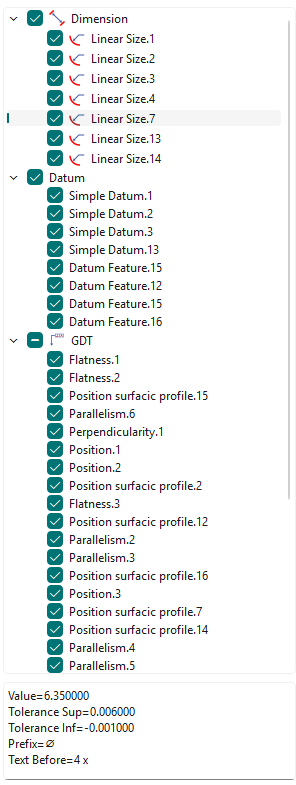
A new tree for PMI analysis is accessible via the Measure function. The PMIs in the tree are gathered by type (Dimension, Datum, GDT,...). Semantic information are also available at the bottom of the tree for a selected PMI.
|
|
|
|
▶️ Watch a video below showing the Activate the PMI view option and the new tree. 
|
|||
|
You can run the measure between two solid faces to modify the value in PMI. This only works for annotations of distances and diameters. |
|||
|
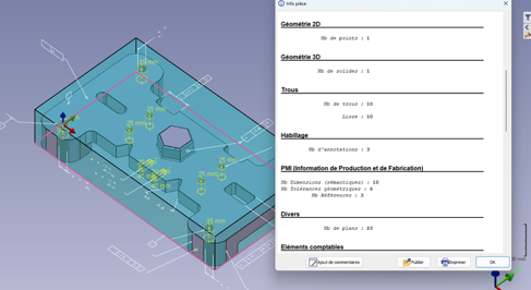
Types of PMIs added in ‘Part Info’ The detail of number of PMIs by type is given:: Nb Dimensions (semantics)
Editing dimension does work only with Dimensions (semantics) |
|
||