
Presentation
|
|
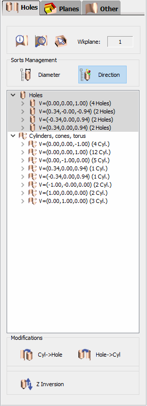
Information and devices regarding the holes of the analysed solid. The holes analysed are displayed in a table and are sorted in 2 types, holes and other elements (cylinders, cones, torus). |
|
|
Zoom selection : when an element (hole, face etc.) is selected in the list, if you can not localize it on the solid, click this button to make a zoom on it. |
|
|
Information : click this icon, and click any element on the solid to get information on it ; you get its coordinates and values and you can localize it in the list of elements where it is underlined. Workplane : to know in which workplane the analysis is done. |
|
Holes Table: The holes are the elements which are supposed to be machined (drilled etc.) The other elements (cylinders, cones, torus) are not supposed to be machined with point to point operations. Sorts Management: Information are given about each element and you can sort them : by Diameter, by Direction, or combine the sorts. In our example, the sort is done by direction. Each line gives you the coordinates of the direction vector of the hole, the highlighted line shows 2 holes which are closed to be vertical, but which are not ! This information is important and very difficult to get without the analysis. 
|
|
|
Modifications: You have the ability to change some data given by the analysis :
|
|
|
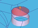
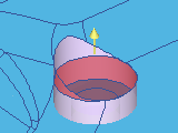
Operations on the holes: To prepare the holes to machining, some functions are available with a right-click on the selected hole(s) : To stop up the hole : creation of a solid face on the hole, to avoid any tool to rough the hole in shape milling. To stop up the 2 sides of the hole
Deletion of the stopping face
To move the stopping face, useful in some special case : the motion is only a Z translation, click the face to move, and then click the new Z directly on an edge of the solid. |
|
|
|
|
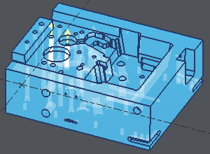
In the following example, we selected in the list the holes that could be roughed by machining done in the reference plane. Then a right-click and choose 'To Stop Up', all the holes are now recovered by solid faces. We chose the red color to distinguish these faces from the solid color. 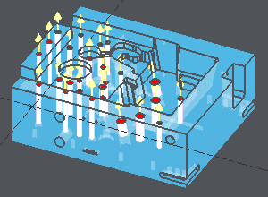
|
Machining:
In Geometry Selection of the Automatic cycles, click the solid to machine and also click the stopping faces defined in Solid Analysis.
You can also do a selection box to show several elements.