
|
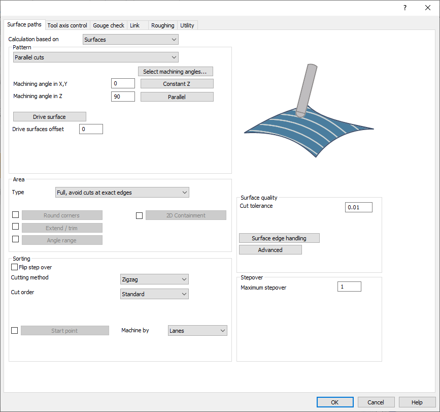
This tab provides the parameters and settings to control the type of toolpaths to be generated to machine the drive surfaces selected. It is categorized into 4 sections:
|
|
Pattern
Drive surfaces are selected surfaces from the CAD model where the toolpath will be generated. The key factor is the normal direction of the faces. The toolpath is created on the front side of the surface, where the surface normal points outward.
Drive surface offset is a virtual offset applied to the drive surface, allowing you to specify the material or stock allowance to keep. This offset expands the drive surfaces in all directions, functioning as a 3D offset.
Several pattern types are available to cater for various situations:
|
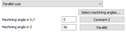
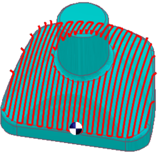
Parallel cuts |
The 'Parallel cuts' option generates toolpaths with slices parallel to each other. The slice orientation is determined by two angles: X-Y,(which rotates the slices around the Z axis) and Z.
|
|
|
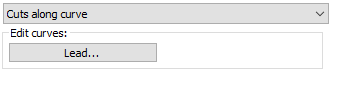
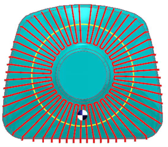
Cuts along curve |
The 'Cuts along curve' pattern allows the user to create a toolpath orthogonal to a drive curve. That means that if the selected curve as 'Lead' is not a straight line the cuts are not parallel to each other.
|
|
|
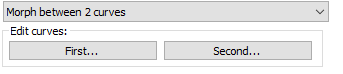
Morph between 2 curves |
This option creates a morph toolpath between two leading curves, inputted as 'First' and 'Second'. Morph means that the generated toolpath gradually interpolates between the two curves and spreads evenly over the surface. This option is well suited for machining steep areas when making moulds.
|
|
|
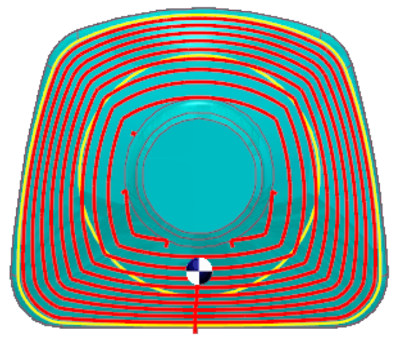
Parallel to multiple curves |
The "Parallel to curve" option generates toolpath segments parallel to the leading curve, with each segment offset from the previous one, rather than simply copied. The curve must align exactly with the surface edge, ideally using the edge itself, to ensure accurate toolpath generation. Misaligned curves can result in incorrect toolpaths. 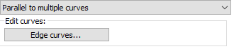
|
|
|
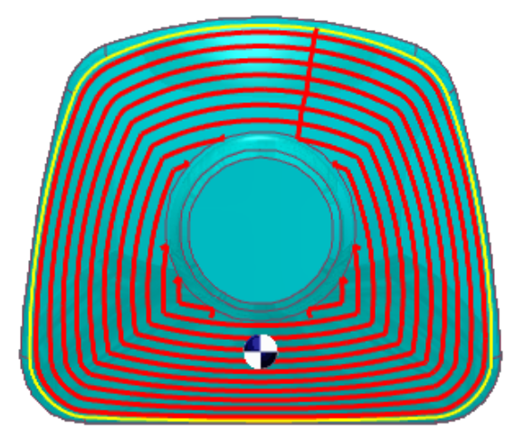
Project curves |
This pattern allows for creating either a user-defined curve or a generic pattern, with options for 2D projections (radial and spiral) and 3D curve projections (offset and user-defined). 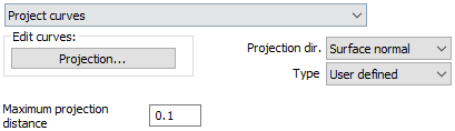
The user must specify the projection direction for the curves, with options including:
|
|
|
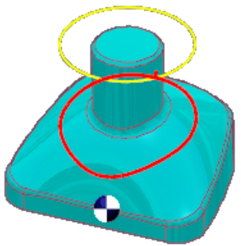
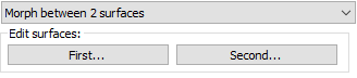
Morph between 2 surfaces |
This option generates a morph toolpath on the drive surface, enclosed by two check surfaces. The toolpath is evenly distributed across the drive surface, making it ideal for machining complex shapes like impeller blades. Bi-Tangency:
|
|
|
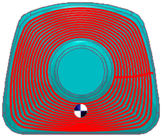
Parallel to surface |
The "Parallel to surface" option creates cuts on the drive surface that are parallel to a leading surface. For the special case when the leading and drive surfaces form an inlaying edge, it is desired to have bi-tangency of the tool with both surfaces. 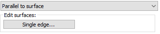
|
|
|
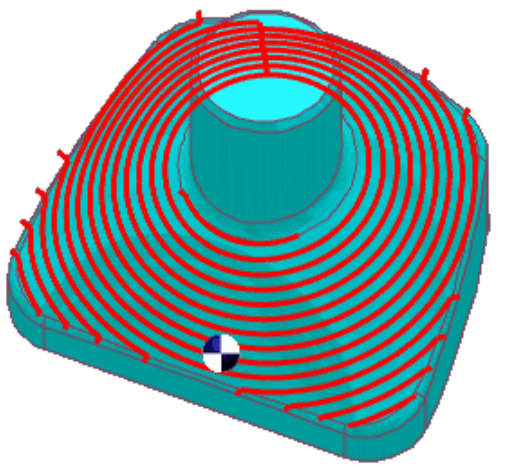
Flowline |
The flowline creates a toolpath aligned to the short or long side, or along the U or V parametric dimensions of the surface. The main advantage is that it doesn't require additional bounding geometries like walls or edge curves. It maintains a constant max step-over distance, even on complex surfaces, and has a fast calculation time. 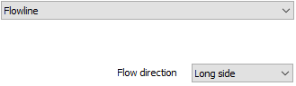
|
|
Area
-
The area types available are as such:
|
Full, avoid cuts at exact edges |
With this option the toolpath is generated on the entire drive surface, avoiding the surface edge. The first cut is not aligned exactly on the surface edge. To calculate the distance from the edge. Changing the maximum step over changes this value accordingly. |
|
Full, start and end at exact surface edge |
This option generates the toolpath on the whole surface and starts and ends at the exact surface edge or the nearest possible position. |
|
Limit cuts by one or two points |
This option allows you to limit the machining between two points on the drive surface, so you can work only on a certain parts of the surface. |
The other parameters are:
|
2D Containment |
The 2D containment contains the toolpath within a selected curve. The projection axis direction is used to project the given curve back to the part. The toolpath is then trimmed by the given curves. Notes: The 2D contour does not have to fit exactly on the surface. It can reach over the edges. You can use multiple contours. The contours must be closed contours. |
|
Angle Range |
For 5-axis parts with undercuts and a complex topology, the definition of shallow and steep areas is more abstract than the definition used for mold-making and 3-axis CAM systems. The Angle range option allows users to define the areas to be machined by an angle range of the surface normal with respect to a user defined axis. The user has the option to machine everything inside the angle interval or outside the interval. |
|
Extend/trim |
With this option you can extend or trim the toolpath. In case of 'extend' the toolpath will be extended tangentially and reaches over the drive surface with a straight line. This line has the same orientation as the last toolpath segment. In case of 'trim' the toolpath will be trimmed along its way. |
|
Round corners |
This option can be set to find small radius areas and inner sharp edges in surface model. Such areas will be left out from toolpath generation. Inside corners can cause 'fish tails' or 'dove tails' in toolpaths. Such fish tails are removed by turning on this switch. This flag can also be considered as a fillet generator. The surface model is rounded (filleted) in the direction of tool path slices with a radius to avoid small radii and inner sharp corners. The applied radius is the main tool radius plus the current stock to leave value. The fillet generation is independent of tool type and shape. In most cases, this switch is used in presence of a ball cutter, lollipop cutter or a conical cutter with ball tip. If swarf machining is applied (side cutting), then this parameter also applies to cylinder or torus cutters. With the additional radius you can increase the fillet radius in surface model. So fillet radius value is the tool radius and the stock remain plus the additional radius. |
Sorting
|
Flip Step Over |
Flip step over changes the cut direction. This can change machining direction from the:
|
|
Cut order |
The cut order defines the sequence of the cuts.
|
|
Cutting Method |
With the cutting method you define whether the machining is 'one way', 'zig zag' or 'spiral'.
|
|
Direction for one way machining |
This feature defines the direction in which the tool moves along the workpiece, depending on the direction of rotation of the machine spindle.
|
|
Machine by Lanes/Regions |
The toolpath generated usually has a topology of multiple contours organized in lanes or regions, on the drive surfaces. When the toolpath is generated on many zones, then it might be preferable to machine all the regions independently. This machining area mode tells the system to follow the machining by lanes or by regions. |
|
Start point |
The start point defines the start position of the first cut and for the following cuts onto the drive surface. This point can be set by
|
Surface quality
|
Cut tolerance |
The cut tolerance is the tolerance for the accuracy of the toolpath. This value is the chordal deviation of the toolpath against the surfaces to be machined. In other words, the toolpath can have a maximum error to the surfaces in the range of plus or minus cut tolerance. |
|
Surface edge handling |
Surface paths are created on individual surfaces. Afterwards toolpath segments are merged together to create longer surface paths. The decision about the merging is currently based on a merge distance. If all toolpath segments on a toolpath slice is merged, it is checked if a closed surface path can be built by connecting the start to the end. The same merge distance value is used for deciding this. So all surface paths that are within closer distance than this value will be merged together. The main benefit is that tiny gaps or overlapping drive surfaces don't cause unexpected behavior in the toolpath. |
|
Advanced |
Machining surface quality depends on toolpath points, which vary with surface curvature. Higher curvature requires more points for accuracy. Chaining tolerance affects toolpath accuracy, with smaller tolerances reducing errors but increasing computation time. Step over calculations can be approximate or exact, influencing surface accuracy. Adaptive cuts and synchronized points improve precision but extend processing time. |
Stepover
Defines the maximum stepover distance between 2 toolpaths. It can be considered as the distance between two scallop crests. The lower the stepover, the higher the surface quality but the machining time also increases.